Phosphor screen and displays systems

a technology of phosphor screen and display system, which is applied in the field of photoluminescent devices, can solve the problems of short life of the projection tube, which is used in such systems, and achieves the effect of improving the thermal and optical performance of the phosphor and improving the quality of the display

Inactive Publication Date: 2010-06-08
ROCKWELL COLLINS INC
View PDF9 Cites 411 Cited by
  • Summary
  • Abstract
  • Description
  • Claims
  • Application Information

AI Technical Summary

Benefits of technology

[0014]In summary, this invention describes display apparatus, display systems, and a display backlight incorporating a phosph...

Problems solved by technology

The CRTs used in such systems, referred to as “P...

Method used


Image

  • Phosphor screen and displays systems
  • Phosphor screen and displays systems
  • Phosphor screen and displays systems

Examples


Embodiment Construction

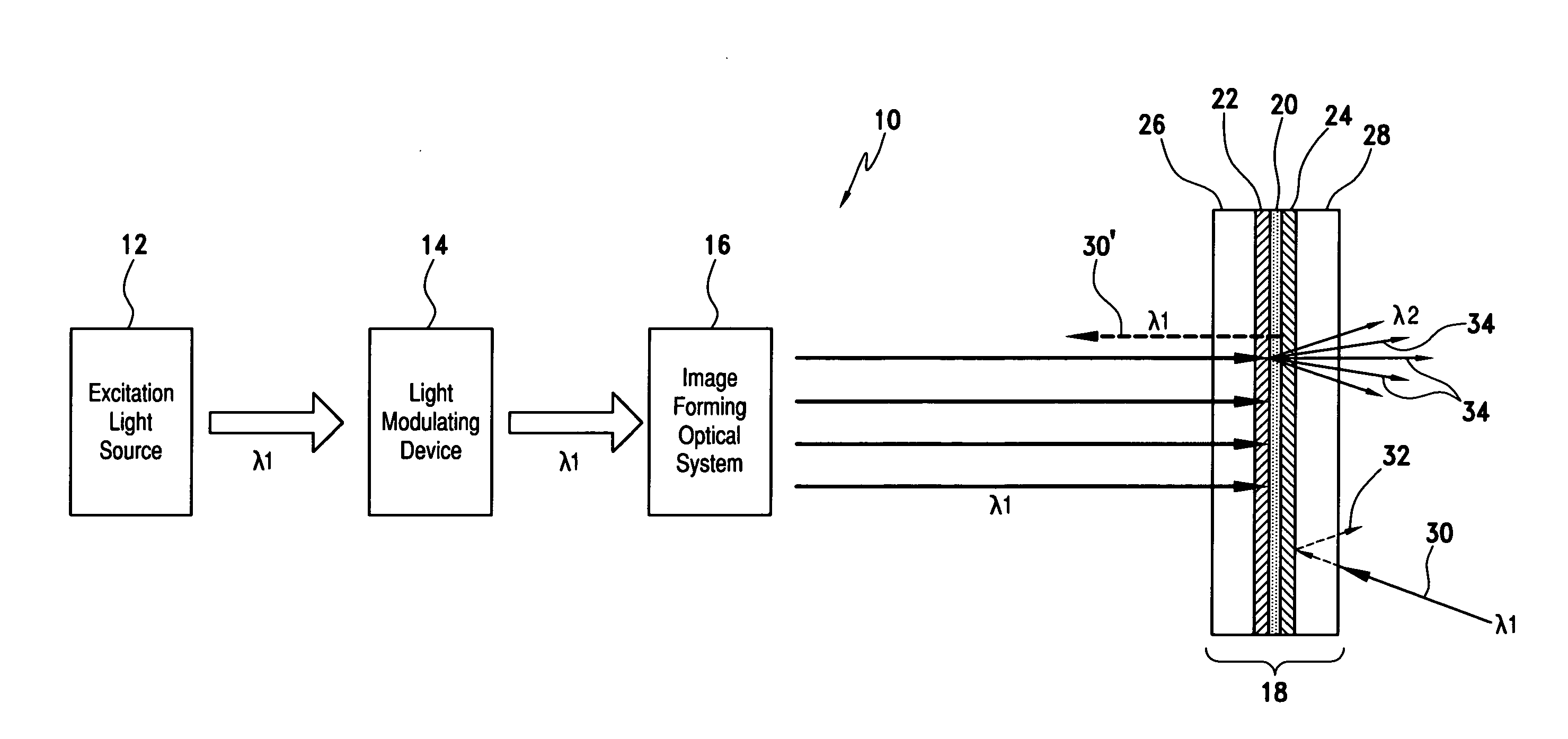
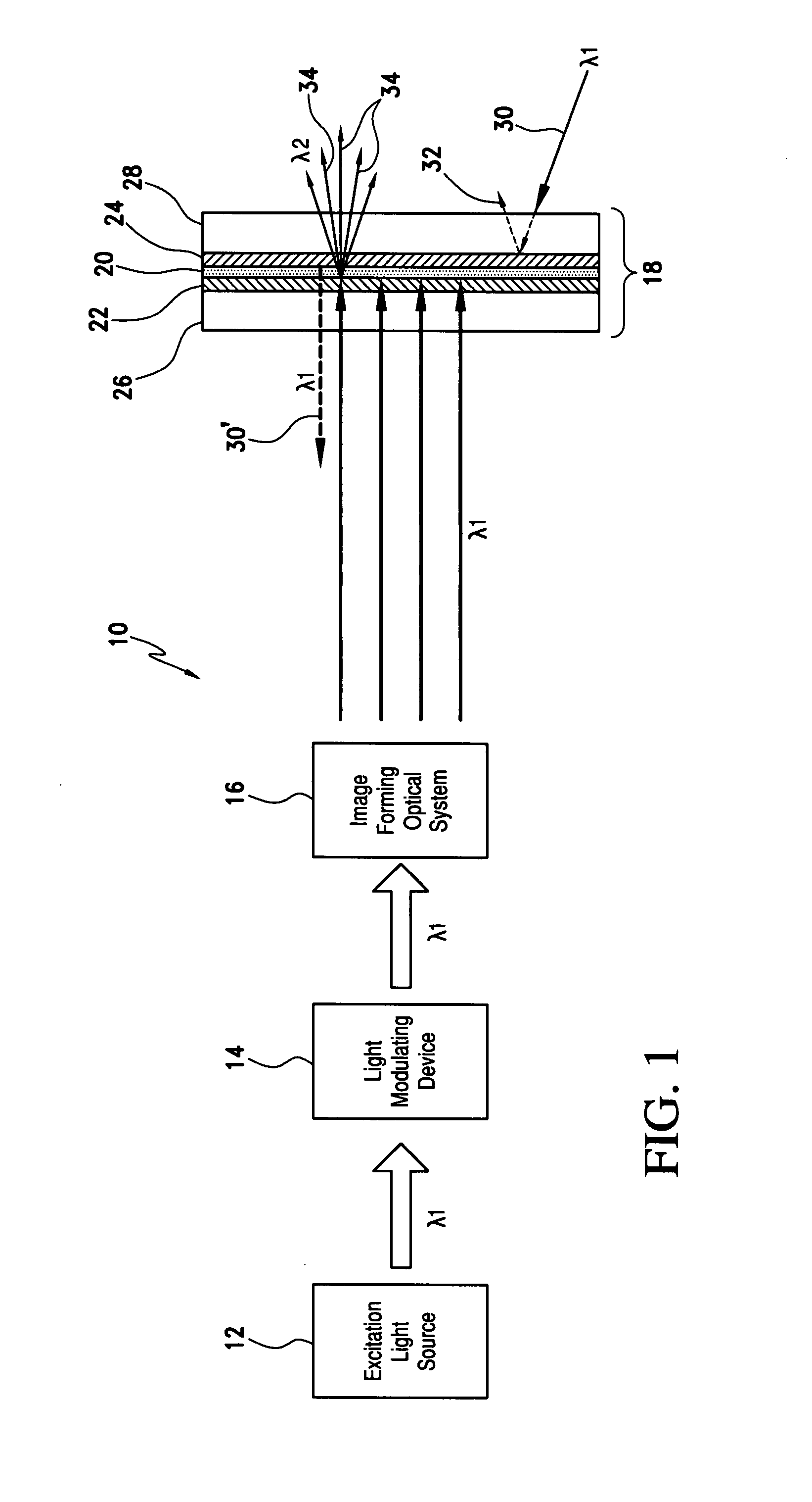
[0023]Referring now to the drawings and the characters of reference marked thereon, FIG. 1 illustrates a visual display system, designated generally as 10, in accordance with the principles of the present invention. In this embodiment, as will be discussed below in detail, a phosphor screen is utilized as an image forming surface.

[0024]An excitation light source 12 provides light in a first wavelength λ1. The excitation light source 12 may be ultraviolet or blue light at wavelength λ1.

[0025]A light modulating device 14 receives light from the excitation light source and modulates the light to form an image. The light modulating device 14 may be, for example, a transmissive liquid crystal display, a reflective liquid crystal display, a micro-mirror array, or a spatial light modulator.

[0026]An imaging forming optical system 16 receives the outputted light from the light modulating device and magnifies and relays the image. The optical system 16 transfers the image formed by or at the ...


PUM


Abstract

A phosphor screen for image forming including phosphor material being excitable by light in a wavelength λ1. The phosphor screen receives an optical image from an image forming optical system and produces the optical image at a second wavelength λ2. The phosphor screen includes a phosphor layer comprising the phosphor material. A short-pass reflective coating is positioned on a first side of the phosphor layer. The short-pass reflective coating transmits the wavelength λ1 and reflects the wavelength λ2. A long-pass reflective coating is positioned on a second side of the phosphor layer. The long-pass reflective coating transmits the wavelength λ2 and reflects the wavelength λ1. A first substrate is positioned over the short-pass reflective coating. The first substrate is formed of optically clear and thermal conductive material. A second substrate is positioned over the long-pass reflective coating. The second substrate is formed of long-pass absorptive optical filter material that transmits the wavelength λ2 and absorbs wavelength λ1 from ambient light to prevent the phosphor layer from being excited by the ambient light. The phosphor screen may alternatively be used for a direct-view visual display apparatus. These principles can also be utilized for backlighting and general illumination applications.

Description

BACKGROUND OF THE INVENTION[0001]1. Field of the Invention[0002]The present invention is related to a photo-luminescent device for producing visible light upon excitation, or for producing visual images if the excitation light is modulated. More particularly, the present invention relates to the packaging of a photo-luminescent device to improve the effective use of the photo-luminescent material. The present invention also relates generally to visual display systems, and more particularly to visual display systems utilizing photo-luminescent materials in the image screen or in the illumination source of the display.[0003]2. Description of the Related Art[0004]Phosphors, as a type of luminescent material, have been used in the devices such as cathode-ray-tubes, x-ray screens, photo-luminescent displays, and lighting or illumination products such as florescent lamps and phosphor-converted white light-emitting diodes (LEDs). Phosphors can absorb the energy from the excitation source a...

Claims


Application Information

Patent Timeline
IPC IPC(8): G02B27/14
CPCG02B27/01G02B5/20G02B2027/0118
Inventor LI, SHU
Owner ROCKWELL COLLINS INC
Why Eureka
Try Eureka