Helmet

a technology for helmets and helmet sleeves, applied in the field of helmets, can solve the problems that the degree of injury of wearers may not be able to be moderated

Inactive Publication Date: 2010-06-15
SHOEI CO LTD
View PDF5 Cites 18 Cited by
  • Summary
  • Abstract
  • Description
  • Claims
  • Application Information

AI Technical Summary

Benefits of technology

[0008]The present invention has been made to solve the problem as described above of the helmet of U.S. Pat. No. 6,263,513, and has as its object to provide a helmet in which the interior of the head protecting body can be ventilated well and / or the air current can be deflected well by a head central / rear ventilator mechanism, a head rear ventilator mechanism, or any other ventilator mechanism, and the degree of injury or the like of the wearer that may increase due to the presence of the ventilator mechanism can be decreased as much as possible.
[0009]According to the first aspect of the present invention, there is provided a helmet comprising a head protecting body to be worn on a head of a helmet wearer to protect the head, the head protecting body being provided with a ventilator mechanism to ventilate an interior of the head protecting body, and at least one ventilator mechanism comprising a shutter member to open / close a vent hole, a shutter attaching member which is attached to an outer surface of the head protecting body so as to attach and hold the shutter member reciprocally, and a cover member which is attached to the shutter attaching member with a plurality of (e.g., two) attaching mechanisms (preferably recess-projection engaging mechanisms) so as to cover the shutter member and the shutter attaching member, wherein the at least one of the plurality of attaching mechanisms comprises a recess-projection engaging mechanism including an engaging projection portion and an engaging hole having a gap, and the engaging projection portion is configured to be relatively pressed into the gap and then relatively inserted and held in the engaging hole through the gap. According to one embodiment of the first aspect of the present invention, the cover member also preferably serves as an air current deflecting member which relatively deflects an air current, relatively flowing along the outer surface of the head protecting body, so as to stabilize the head protecting body.
[0011]According to the above first and second aspects of the present invention, when the wearer puts on the helmet and drives on a motor cycle, the interior of the head protecting body can be ventilated well by the ventilator mechanism. Even when the motorcycle falls during driving and the cover member or air current deflecting member catches on the ground surface or the like, the degree of injury of the wearer that may increase due to the presence of the ventilator mechanism can be decreased as much as possible. According to the first aspect of the present invention, damages or contamination of the shutter member and shutter attaching member can be prevented effectively. According to one embodiment of the first aspect of the present invention and according to the above second aspect of the present invention, when the wearer puts on the helmet and drives on the motor cycle, the air current deflecting member relatively deflects the air current flowing relatively along the outer surface of the head protecting body. Thus, the head protecting body can be stabilized.
[0013]According to the above first and second aspects of the present invention, at least another one of the plurality of attaching mechanisms can comprise a simple plug-in recess-projection engaging mechanism including a second engaging projection portion and a second engaging hole in which the second engaging projection portion is to be relatively inserted and held, the second engaging projection portion which is relatively inserted and held in the second engaging hole is configured to readily come out from the second engaging hole substantially in a direction of depth of the second engaging hole, and the second engaging projection portion is configured to relatively come out from the second engaging hole substantially in the same direction as a direction in which the engaging projection portion relatively comes out from the engaging hole through the gap. With this arrangement, when the wearer puts on the helmet and drives on the motor cycle, if the motorcycle falls and the cover member or air current deflecting member catches on the ground surface or the like, the cover member or air current deflecting member can be effectively removed from the head protecting body with a comparatively simple arrangement.
[0015]According to the above first and second aspects of the present invention, preferably, the cover member or air current deflecting member has a substantially end-lug-hole-shaped engaging opening comprising the engaging hole, the gap, and an engaging auxiliary hole which continues to the engaging hole through the gap and is larger than the engaging hole, the cover member or air current deflecting member has a cover portion which covers the engaging auxiliary hole, and an inner surface of the cover portion decreases to gradually taper from the gap side of the engaging auxiliary hole toward an opposite side. With this arrangement, when the cover member or air current deflecting member is to be removed in the above manner, the cover portion is relatively separated from the engaging projection portion effectively. Thus, the cover member or air current deflecting member can be removed further effectively.
[0016]According to the above first and second aspects of the present invention, the cover portion can substantially form a ¼ spindle shape which can be obtained by halving a substantially spindle-shaped hollow body in both a longitudinal direction and a direction of diameter. According to the above first and second aspects of the present invention, a flexural rigidity of a material that forms the engaging projection portion preferably falls within a range of 30 MPa to 80 MPa and more preferably within a range of 40 MPa to 60 MPa. With this arrangement, the engaging projection portion can be relatively inserted in the engaging hole through the gap or can be relatively pulled out from the engaging hole through the gap effectively.

Problems solved by technology

Hence, in the case of the helmet of U.S. Pat. No. 6,263,513, for example, when the motorcycle falls, the degree of the injury of wearer may not be able to be moderated due to the presence of the head central / rear ventilator (particularly its cover / air current deflecting member).

Method used


Image

  • Helmet
  • Helmet
  • Helmet

Examples


Embodiment Construction

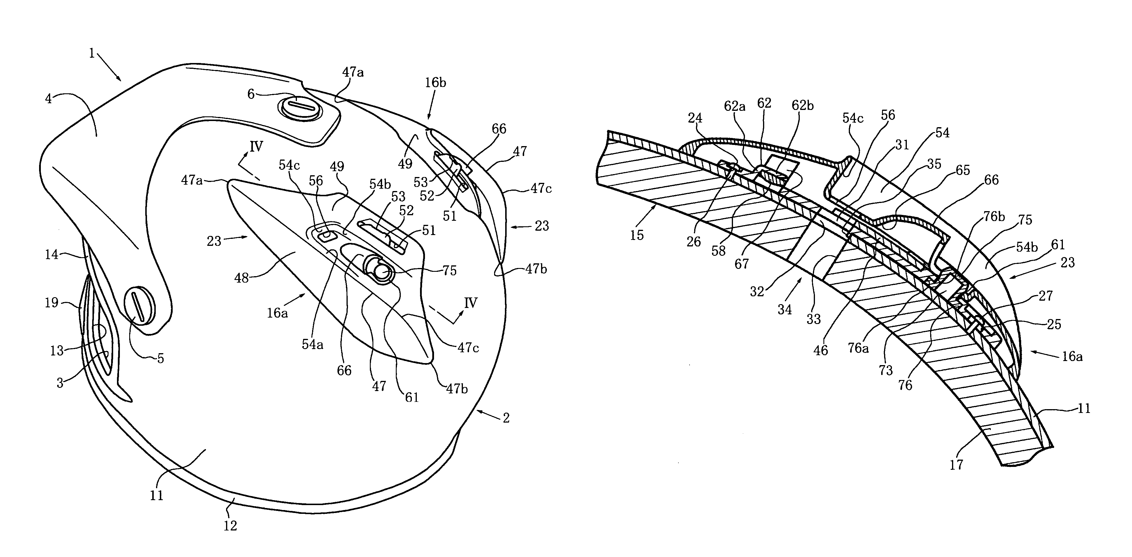
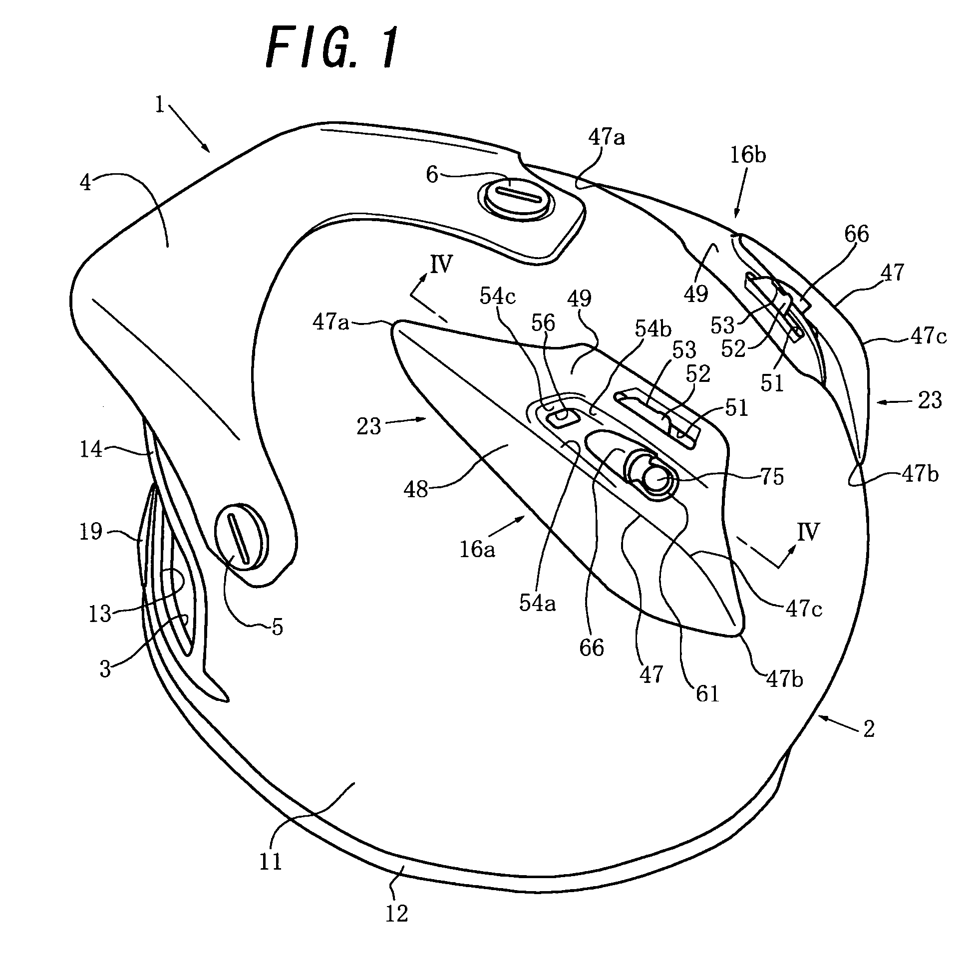
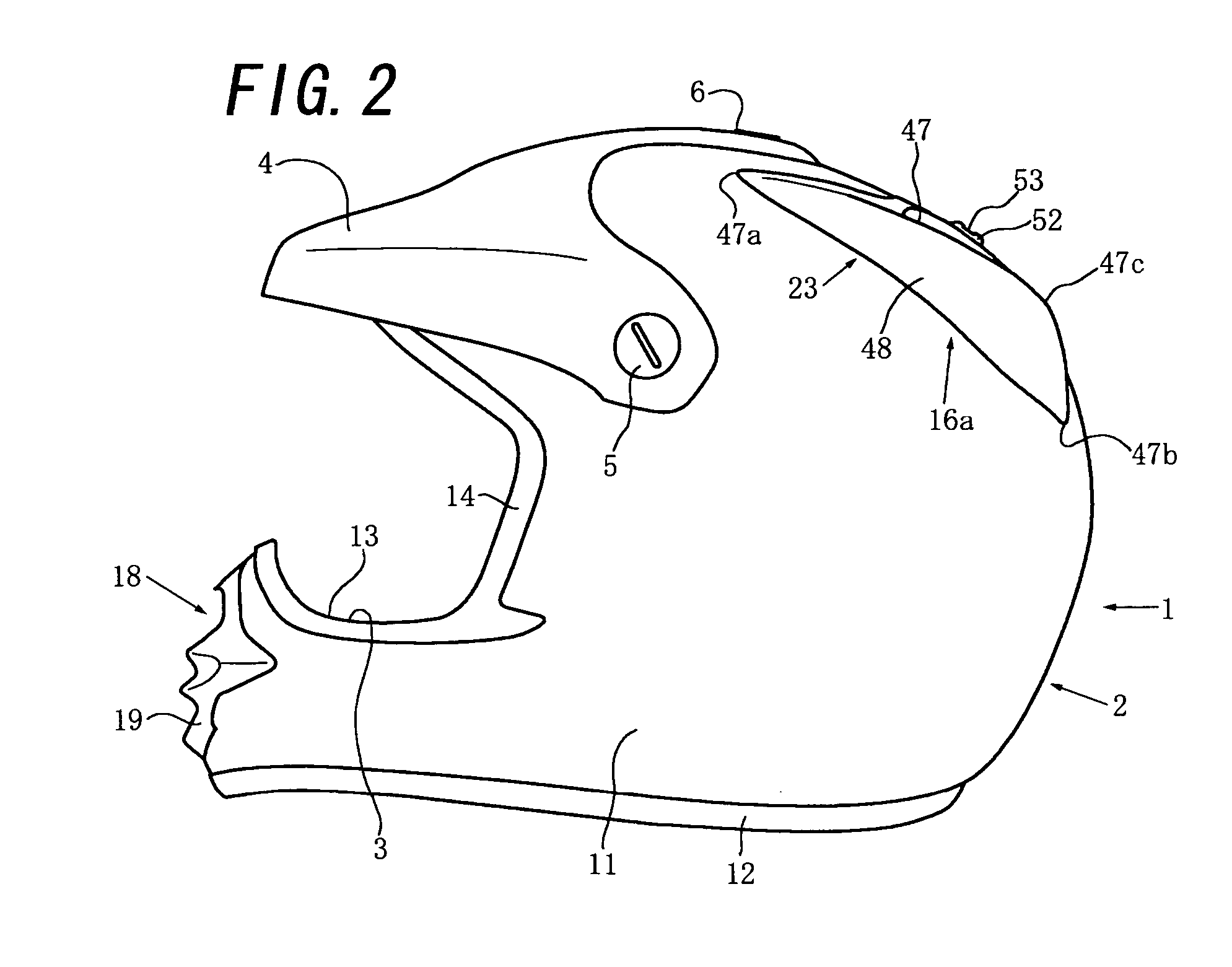
[0026]An embodiment in which the present invention is applied to an off-road driving full-face-type helmet will be described in “1. General Description of Helmet as a Whole” and “2. Specific Description of Head Rear Ventilator Mechanism” with reference to the accompanying drawings.

1. General Description of Helmet as a Whole

[0027]As shown in FIGS. 1 to 3, an off-road driving full-face-type helmet 1 such as a motocross helmet includes a full-face-type cap-like head protecting body 2 to be worn on the head of a wearer, a window opening 3 formed in the front surface of the head protecting body 2 to oppose a portion (i.e., the face) between the forehead and chin of the wearer, a visor 4 which projects forward above the window opening 3 from the head protecting body 2, and a pair of left and right chin straps (not shown) attached to the inside of the head protecting body 2. As has been known, the visor 4 can be made of an opaque, translucent, or transparent soft material such as polyethyl...


PUM


Abstract

A helmet which can ventilate the interior of a head protecting body well by a ventilator mechanism and can decrease the degree of injury or the like of a wearer that may increase by the presence of the ventilator mechanism. At least one of a plurality of attaching mechanisms that attach a cover member or air current deflecting member to the shutter attaching member of the ventilator mechanism includes an engaging projection portion and an engaging hole having a gap. The engaging projection portion is configured to be relatively pressed into the gap and then relatively inserted and held in the engaging hole through the gap.

Description

TECHNICAL FIELD[0001]The present invention relates to a helmet which comprises a head protecting body to be worn on the head of a helmet wearer (to be merely referred to as a “wearer” in this specification) such as a motorcycle rider and in which a ventilator mechanism to ventilate the interior of the head protecting body is provided to the head protecting body.BACKGROUND OF THE INVENTION[0002]As a full-face-type helmet in which a ventilator mechanism is provided to a head protecting body to ventilate the interior of the head protecting body as described above, for example, one described in U.S. Pat. No. 6,263,513 is conventionally known. The full-face-type helmet of U.S. Pat. No. 6,263,513 comprises a head central / rear ventilator mechanism at a head central / rear region including the vertex region (the vertex region substantially opposes the vertex of the wearer) and the upper portion of the back head region (the back head region substantially opposes the back part of the head of th...

Claims


Application Information

Patent Timeline
Patent Type & Authority Patents(United States)
IPC IPC(8): A42B1/06A42B1/08A63B71/10
CPCA42B3/283
Inventor TSURUMI, MASAYUKI
Owner SHOEI CO LTD
Why Eureka
Try Eureka