Drenching shower head

a shower head and shower head technology, applied in the field of shower head, can solve the problems of rotating or spinning of the turbine in the channel

Active Publication Date: 2010-06-22
WATER PIK INC
View PDF892 Cites 99 Cited by
  • Summary
  • Abstract
  • Description
  • Claims
  • Application Information

AI Technical Summary

Problems solved by technology

Water flowing into a flow channel housing a turbine typically impacts one or more blades of the turbine, causing the turbine to rotate or spin in the channel.

Method used


Image

  • Drenching shower head
  • Drenching shower head
  • Drenching shower head

Examples


second embodiment

4. Second Embodiment

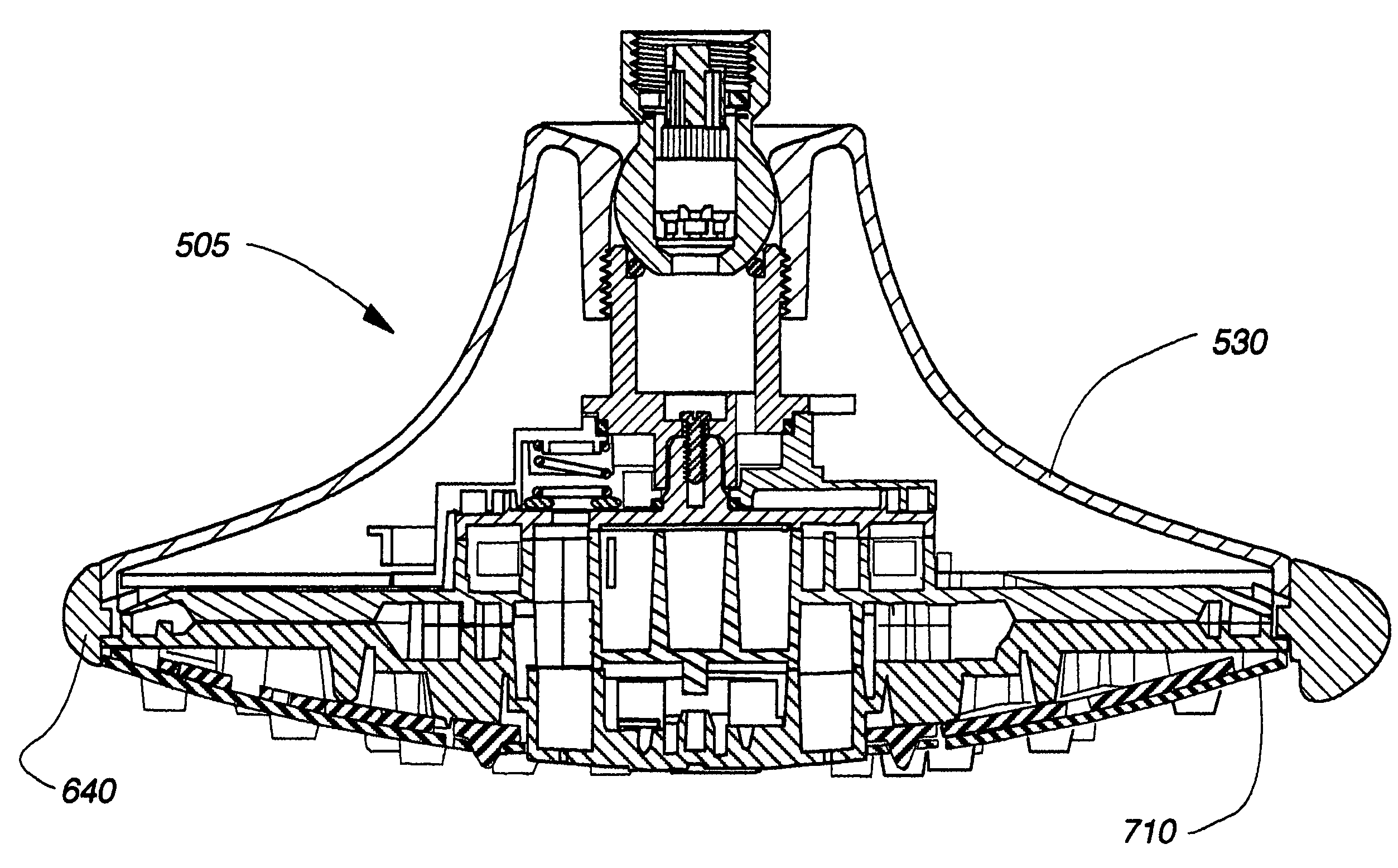
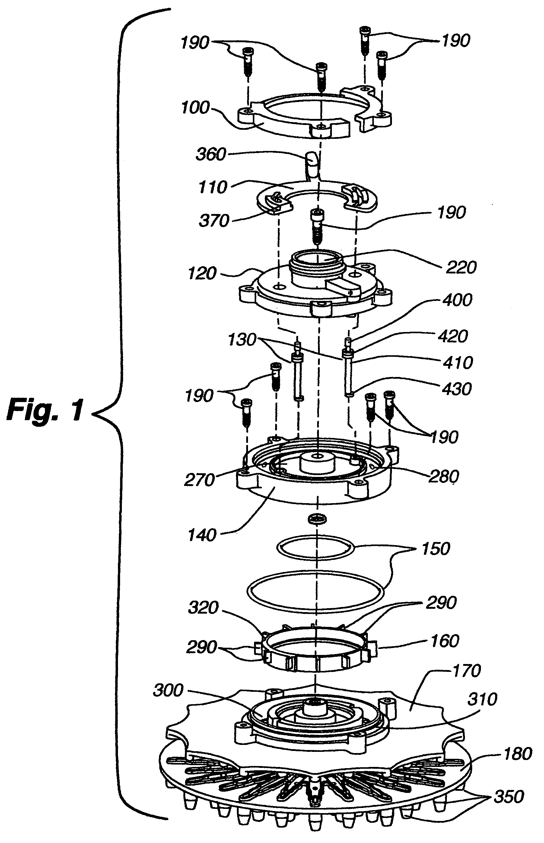
[0105]FIGS. 6-37 depict a second embodiment of a drenching shower head 505. FIG. 6 depicts the shower head in an exploded view, such that various internal elements of the shower head may be seen from rear to front. This embodiment of a drenching shower head 505 includes a filter screen 500, a flow regulator 510, pivot ball 520, base cone 530, o-ring 540, pivot ball mount 550, second o-ring 560, pivot ball housing 570, spring 580, cup seal 590, assorted screws 600, plunger 610, seal 620, third o-ring 630, mode ring 640, backplate cap 650, turbine 660, backplate 670, second turbine 680, frontplate 690, nozzle web 700 and face plate 710.

[0106]FIGS. 7-10 depict various cross-sectional views of the present shower head 505. Each cross-sectional view is taken along a different plane intersecting the shower head. FIGS. 7-10 generally depict the inner connections and relative positioning of the various portions of the shower head listed with respect to FIG. 6.

[0107]For ex...


PUM


Abstract

An improved shower head having multiple modes of operation. The shower head may include a first turbine and turbine, each disposed within a unique flow channel. The first and second turbines may interrupt water flow through their respective flow channels, thereby providing at least one pulsating water spray emanating from the shower head. The shower head may include a third flow channel having no turbine disposed therein, such that water flowing through the third flow channel is not interrupted and thus emitted from the shower head as a drenching spray.

Description

CROSS REFERENCE TO RELATED APPLICATION[0001]This non-provisional application claims benefit under 35 U.S.C. §119(e) to provisional application No. 60 / 606,579, filed Sep. 1, 2004, entitled “Drenching Shower Head,” which is hereby incorporated by reference in its entirety.BACKGROUND OF THE INVENTION[0002]1. Technical Field[0003]The present invention relates generally to showerheads, and more specifically to a showerhead having pulsating spray and drenching modes of operation.[0004]2. Background Art[0005]Generally, shower heads are used to direct water from the home water supply onto a user for personal hygiene purposes. Showers are an alternative to bathing in a bath tub.[0006]In the past, bathing was the overwhelmingly popular choice for personal cleansing. However, in recent years showers have become increasingly popular for several reasons. First, showers generally take less time than baths. Second, showers generally use significantly less water than baths. Third, shower stalls and...

Claims


Application Information

Patent Timeline
Patent Type & Authority Patents(United States)
IPC IPC(8): B05B17/04
CPCB05B1/1654B05B3/049B05B3/0495B05B3/04B05B1/18B05B15/067B05B15/654
Inventor MACAN, AARON DAMIANQUINN, MICHAEL J.
Owner WATER PIK INC
Why Eureka
Try Eureka