Spa control system

a control system and spa technology, applied in the field of spa control systems, can solve the problems of difficult accurate control of temperature, complicated system design of spa control system, inherently corroding atmosphere surrounding the control system of the spa unit, etc., and achieve the effect of accurately and efficiently controlling the spa operation and not adversely affecting the corroding environment surrounding the spa

Inactive Publication Date: 2005-12-13
DYMAS FUNDING COMPANY +1
View PDF198 Cites 129 Cited by
  • Summary
  • Abstract
  • Description
  • Claims
  • Application Information

AI Technical Summary

Benefits of technology

[0006]The present invention overcomes the foregoing difficulties by providing a spa control system which accurately and efficiently controls the operation of the spa and is not adversely affected by the corrosive environment surrounding the spa. The spa temperature control system generally comprises a heating element, a sensor for detecting the temperature of the water, and a microcomputer for processing signals generated by said sensor and for activating and deactivating the heating element. In one embodiment of the invention, the microc

Problems solved by technology

The design of systems to control spas is complicated by the environment of the spa.
Typically, spa control systems contain heating elements, controls, switches, and wiring harnesses which deteriorate when exposed to moisture or extreme levels of humidity and a hostile chemical environment.
Since the chemically treated, heated water of the spa raises the humidity level and produces corrosive gases, the atmosphere surrounding the controls of the spa unit is inherently corrosive to spa control systems.
This temperature is difficult to accurately c

Method used


Image

  • Spa control system
  • Spa control system
  • Spa control system

Examples


Embodiment Construction

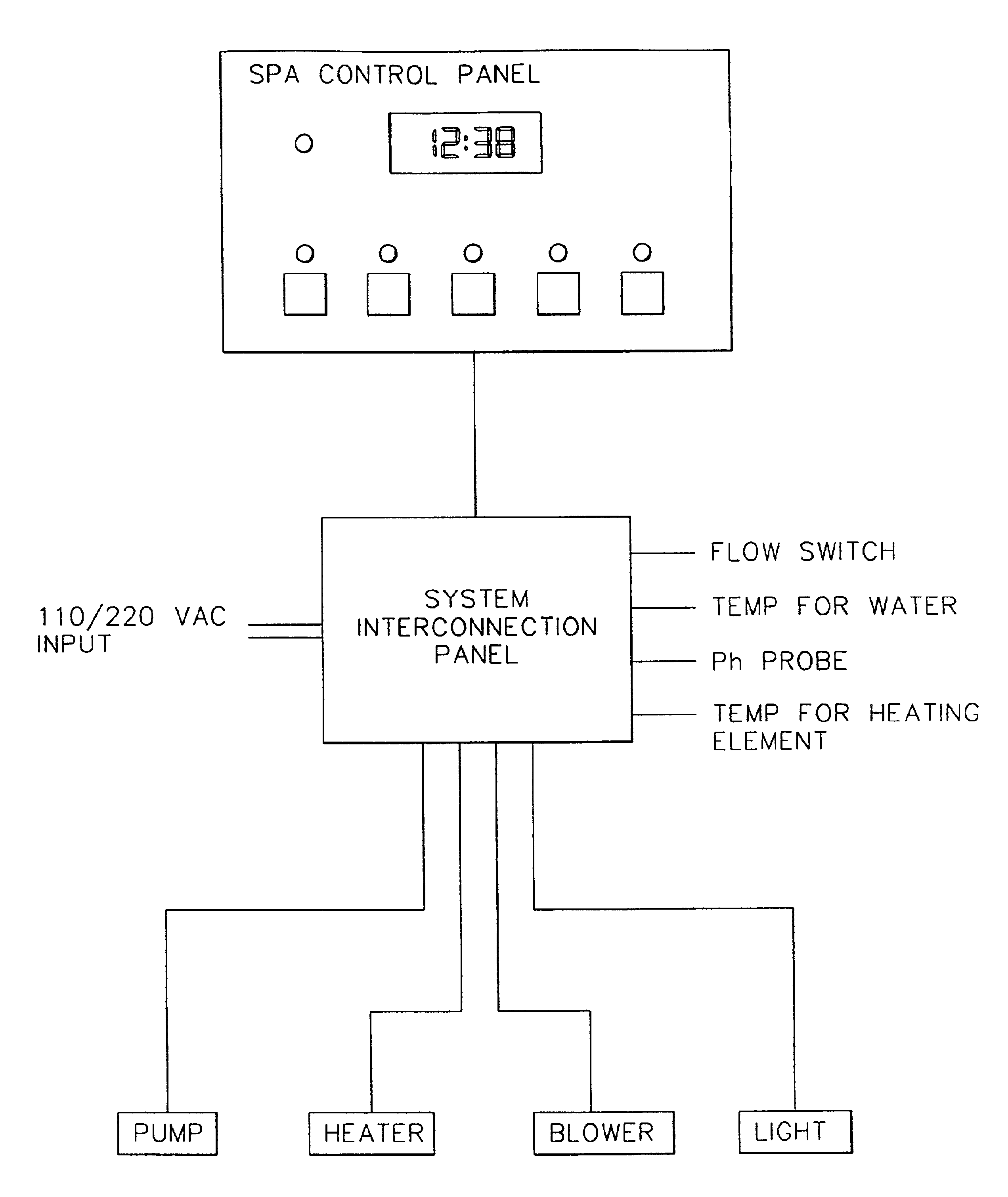
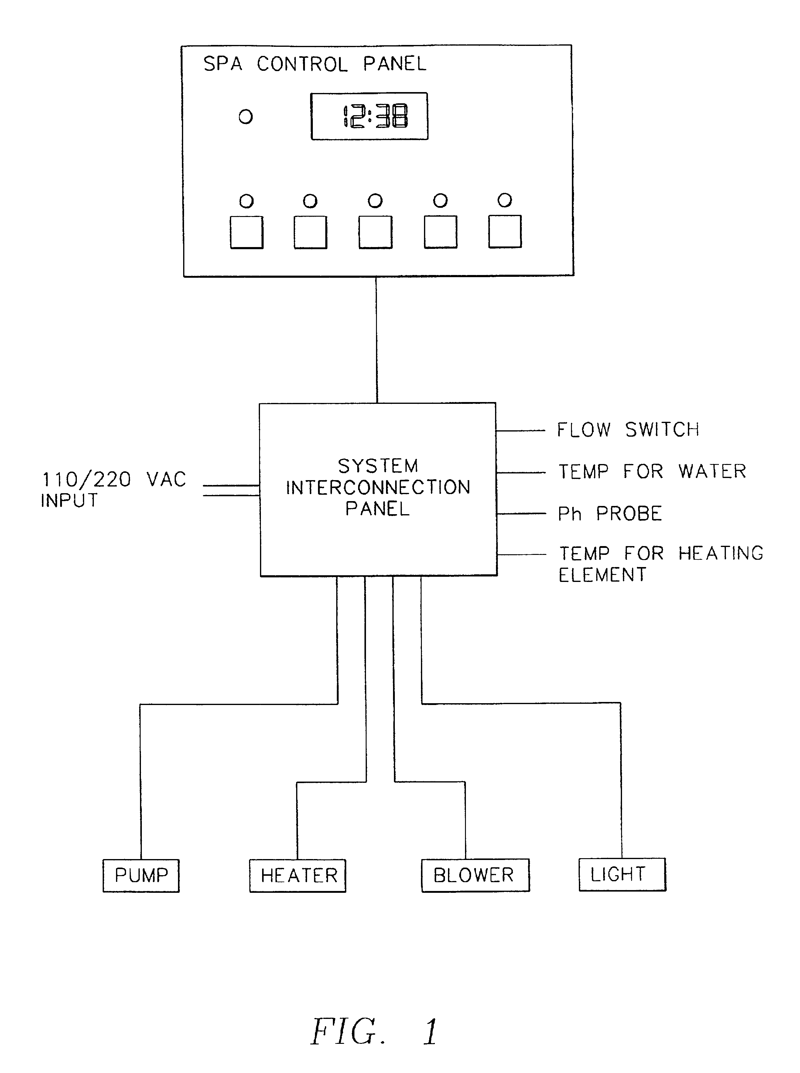
[0015]FIGS. 1 and 2 illustrate a block diagram of the overall spa control system. The spa control system uses an intelligent microcomputer 10 to monitor and control the operation of the spa. The system uses solid state electronic components which eliminate many of the problems associated with traditional mechanical timer and relay control systems. The use of solid state electronic components increases the reliability of the system and reduces the maintenance necessary to maintain the spa in operable condition.

[0016]Referring to FIGS. 1 and 14, the external system generally comprises a spa control panel 12 which is connected to a system interconnection panel 14. The system interconnection panel 14 is also connected to power input 16, to various sensors which detect parameters such as flow rate 18, temperature 20, 21 and pH 22 of the water, and also the mechanical and electrical components of the spa, such as the pump 24, heater 26, blower 28, and lights 30. The heater 26 may be inter...


PUM


Abstract

An improved spa control system is disclosed. The invention describes a spa control system which calculates the time required to heat the water in the spa system to a desired temperature. From that information, the heating rate of the spa system can be determined, and the heating element of the spa system can be activated at the proper time to raise the temperature of the water to a selected temperature by a desired time. The spa system also monitors information which might show errors in the operation of the spa system such as a blockage in the flow of water over the heating element in the spa system.

Description

[0001]This application is a continuation of U.S. patent application Ser. No. 08 / 822,179 filed Mar. 20, 1997, now U.S. Pat. No. 6,253,227, which is a continuation of U.S. application Ser. No. 08 / 703,177 filed Aug. 23, 1996, now abandoned, which is a continuation of U.S. application Ser. No. 08 / 327,927 filed Oct. 24, 1994, now U.S. Pat. No. 5,559,720, which is a continuation of U.S. patent application Ser. No. 08 / 225,282 filed Jan. 11, 1994, now U.S. Pat. No. 5,361,215, which is a continuation of U.S. patent application Ser. No. 07 / 224,869 filed Jul. 26, 1988, now abandoned, which is a continuation-in-part of U.S. patent application Ser. No. 07 / 054,581, filed May 27, 1987, now abandoned, each of the above related applications and patents being incorporated herein by reference.FIELD OF THE INVENTION[0002]This invention relates to the development of a spa control system. More particularly, this invention relates to a spa control system which uses an interconnection panel and a control p...

Claims


Application Information

Patent Timeline
IPC IPC(8): A61H33/00G05D23/20
CPCA61H33/0095G05D23/2028G05D23/1931G05D23/20
Inventor TOMPKINS, MICHAEL E.GREEN, MICHAEL J.
Owner DYMAS FUNDING COMPANY
Why Eureka
Try Eureka