Electric power terminal feed-through
a technology of electric power terminals and feed-throughs, which is applied in the direction of electrical apparatus casings/cabinets/drawers, machines/engines, etc., can solve the problems of feed-through damage, leakage, and inability to integrate the insulating seals
- Summary
- Abstract
- Description
- Claims
- Application Information
AI Technical Summary
Benefits of technology
Problems solved by technology
Method used
Image

Examples
first embodiment
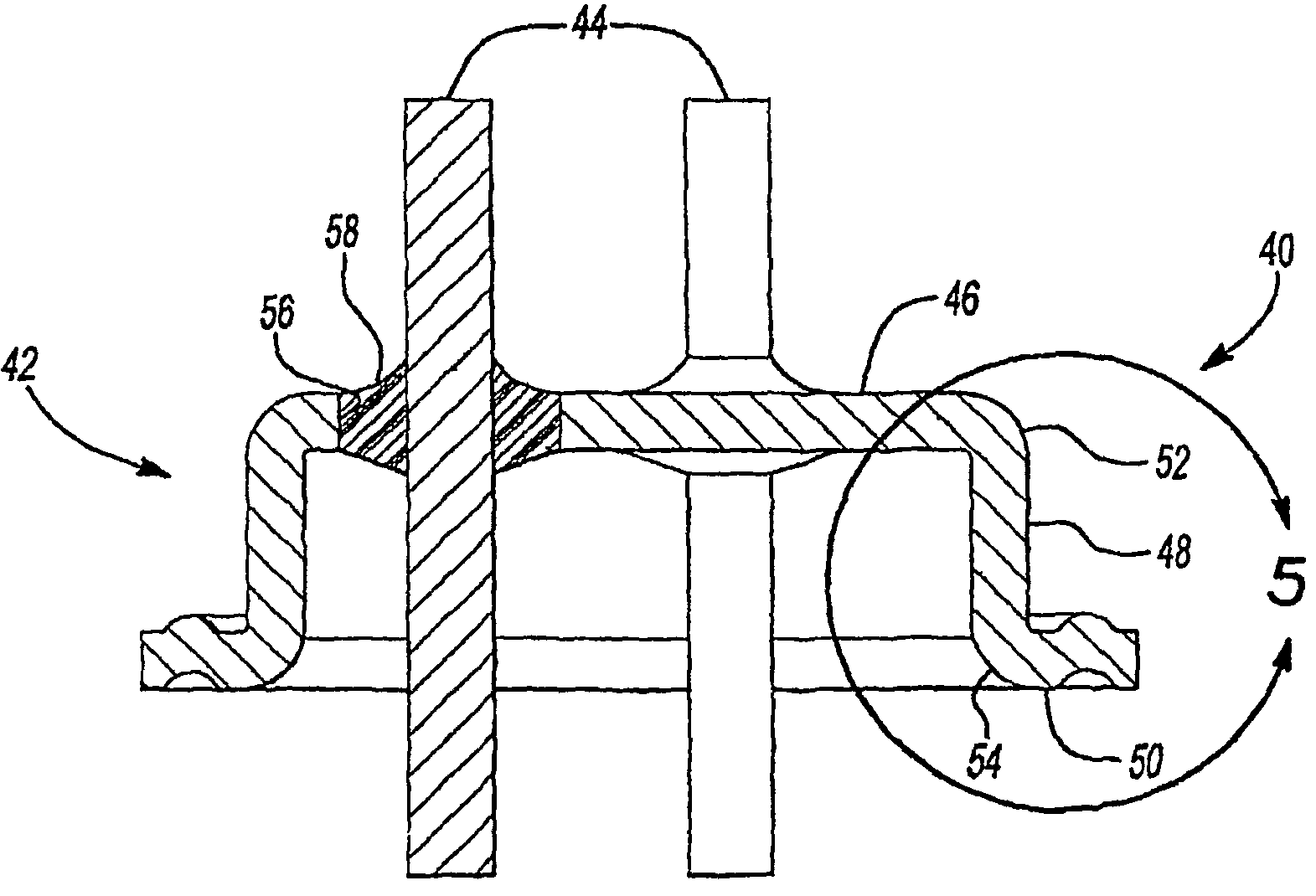
[0035]Referring to FIGS. 3 and 4, an electric power terminal feed-through constructed in accordance with the present disclosure is illustrated and generally indicated by reference numeral 40. The power terminal feed-through 40 includes a metallic body 42, and one or more current conducting pins 44 extending through the metallic body 42 (three conducting pins 44 are shown in FIG. 3). The current-conducting pins 44 define a pin circle diameter φ1, which is the dimension of the circle passing through the centers of the current-conducting pins 44 as they are centered and spaced on a longitudinal axis of the power terminal feed-through 40. The current conducting pins 44 are preferably made from steel, stainless steel, or a copper-cored steel wire.
[0036]As shown, the metallic body 42 is cup-shaped and includes a bottom wall 46, a cylindrical sidewall 48 disposed around the bottom wall 46, and an annular lip 50 extending from the cylindrical sidewall 48. The cylindrical sidewall 48 include...
second embodiment
[0042]Referring to FIGS. 10 to 12, a power terminal feed-through constructed in accordance with the present disclosure is illustrated and generally indicated by reference numeral 70.
[0043]Similar to the first embodiment, the power terminal feed-through 70 includes a metallic body 72 and one or more current conducting pins 74 passing through the metallic body 72, wherein the metallic body 72 has a cylindrical sidewall 76 and an annular lip 78 extending radially and outwardly from the cylindrical sidewall 76. Unlike the metallic body 42 of the first embodiment, however, the metallic body 72 of this embodiment does not have a bottom wall. Instead, the metallic body 72 includes a radiused edge 80 connected to a first end 82 of the cylindrical sidewall 76. The radiused edge 80 defines an opening 84. The opening 84 is so dimensioned that one or more current-conducting pins 74 pass through the opening 84 with a proper distance therebetween. The proper distance refers to the minimum electri...
fourth embodiment
[0050]Referring to FIGS. 16 and 17, an electric power terminal feed-through in accordance with the present disclosure is illustrated and generally indicated by reference numeral 140. The electric power terminal feed-through 140 includes a metallic body 142 and one or more current-conducting pins 144 passing through the metallic body 142.
[0051]The metallic body 142 includes an outer cylindrical sidewall 146, an annular lip 148, an inner cylindrical sidewall 150 and a connecting wall 152. The inner cylindrical side wall 150 defines a receiving space 154 for receiving a single insert seal 88 therein. The annular lip 148 is flared out from the outer cylindrical sidewall 146 to form an angle of about 135° relative to the outer cylindrical sidewall 146. The outer cylindrical sidewall 146 and the inner cylindrical sidewall 150 define a gap 156.
[0052]As shown in FIG. 18, the weld 64 is formed at the transition portion 160 between the outer cylindrical sidewall 146 and the annular lip 148. B...
PUM
 Abstract
Description
Claims
Application Information
 - R&D
- Intellectual Property
- Life Sciences
- Materials
- Tech Scout
- Unparalleled Data Quality
- Higher Quality Content
- 60% Fewer Hallucinations
Browse by: Latest US Patents, China's latest patents, Technical Efficacy Thesaurus, Application Domain, Technology Topic, Popular Technical Reports.
© 2025 PatSnap. All rights reserved.Legal|Privacy policy|Modern Slavery Act Transparency Statement|Sitemap|About US| Contact US: help@patsnap.com