
Radio reception system with automatic tuning

a technology of automatic tuning and reception system, applied in the field of radio receiving system, can solve the problems of unsatisfactory reception on the presently set frequency, receivers that do not provide uninterrupted listening, and users are extremely annoying, and achieve the effect of facilitating data reception

Inactive Publication Date: 2010-06-29
AG BECKER & CO
View PDF25 Cites 8 Cited by
  • Summary
  • Abstract
  • Description
  • Claims
  • Application Information

AI Technical Summary

Benefits of technology

This approach ensures uninterrupted and improved radio reception by systematically finding and switching to the best available frequency, reducing the number of reception interruptions and maintaining optimal signal quality, even in systems with multiple receivers and antennas.

Problems solved by technology

Even when a driver travels over large distances, which exceed the range of an individual USW broadcast station, he is thus able to continue listening to a transmitter without having to manually seek an alternate frequency when reception on the presently set frequency becomes unsatisfactory.
However, these receivers do not provide uninterrupted listening, since the process of seeking a frequency of the same transmitter can take considerable time, within which the receiver repeatedly tunes to other frequencies and checks whether the transmitter received there is identical to the original one.
If such an interruption automatically occurs during a transmission of traffic reports, such as warnings of a traffic jam, etc., this is extremely annoying for the user, even if the interruption takes only a few seconds.
If the quality of a receiver becomes so bad that it must seek a new reception frequency, this change is inaudible to a user of the radio reception system as long as there are other receivers on the ring that can output a reception signal with satisfactory quality.
A problem with this system is that since every receiver seeks an alternative frequency only until it has found one with satisfactory quality, the reception signal circulating on the ring generally does not constantly have the best quality, which is achievable by taking into account all the available frequencies of a transmitter.

Method used


Image

  • Radio reception system with automatic tuning
  • Radio reception system with automatic tuning
  • Radio reception system with automatic tuning

Examples


Embodiment Construction

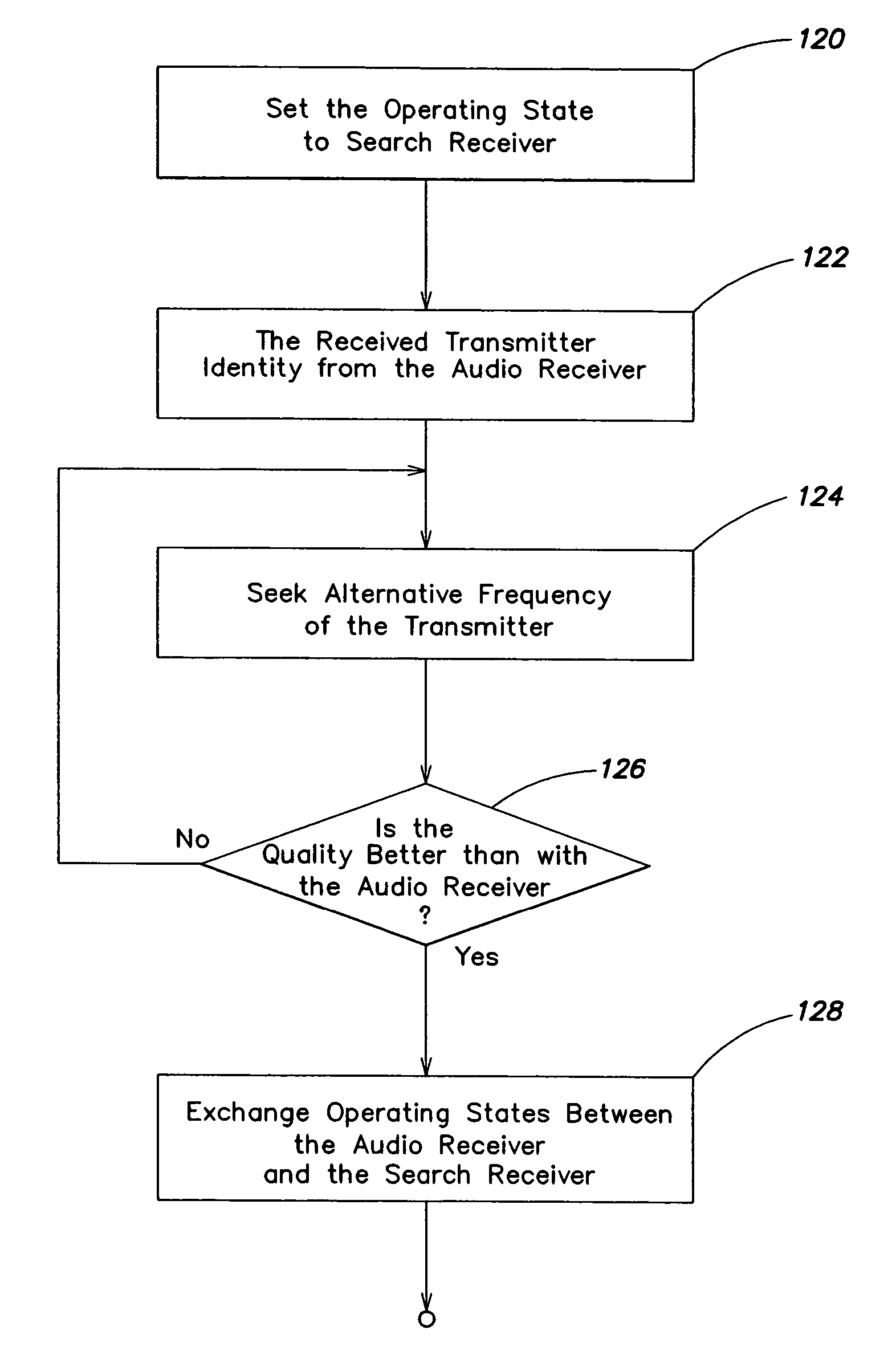
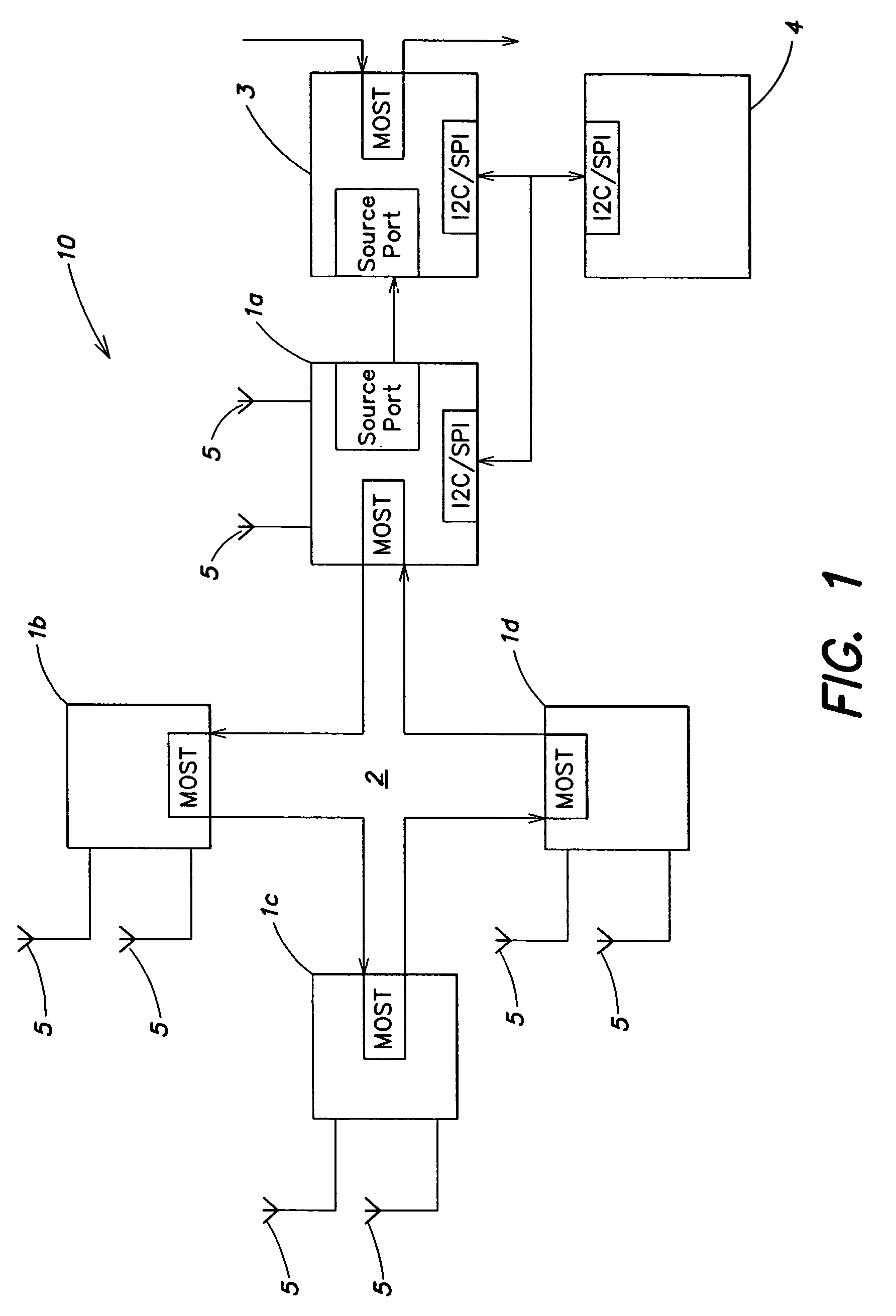
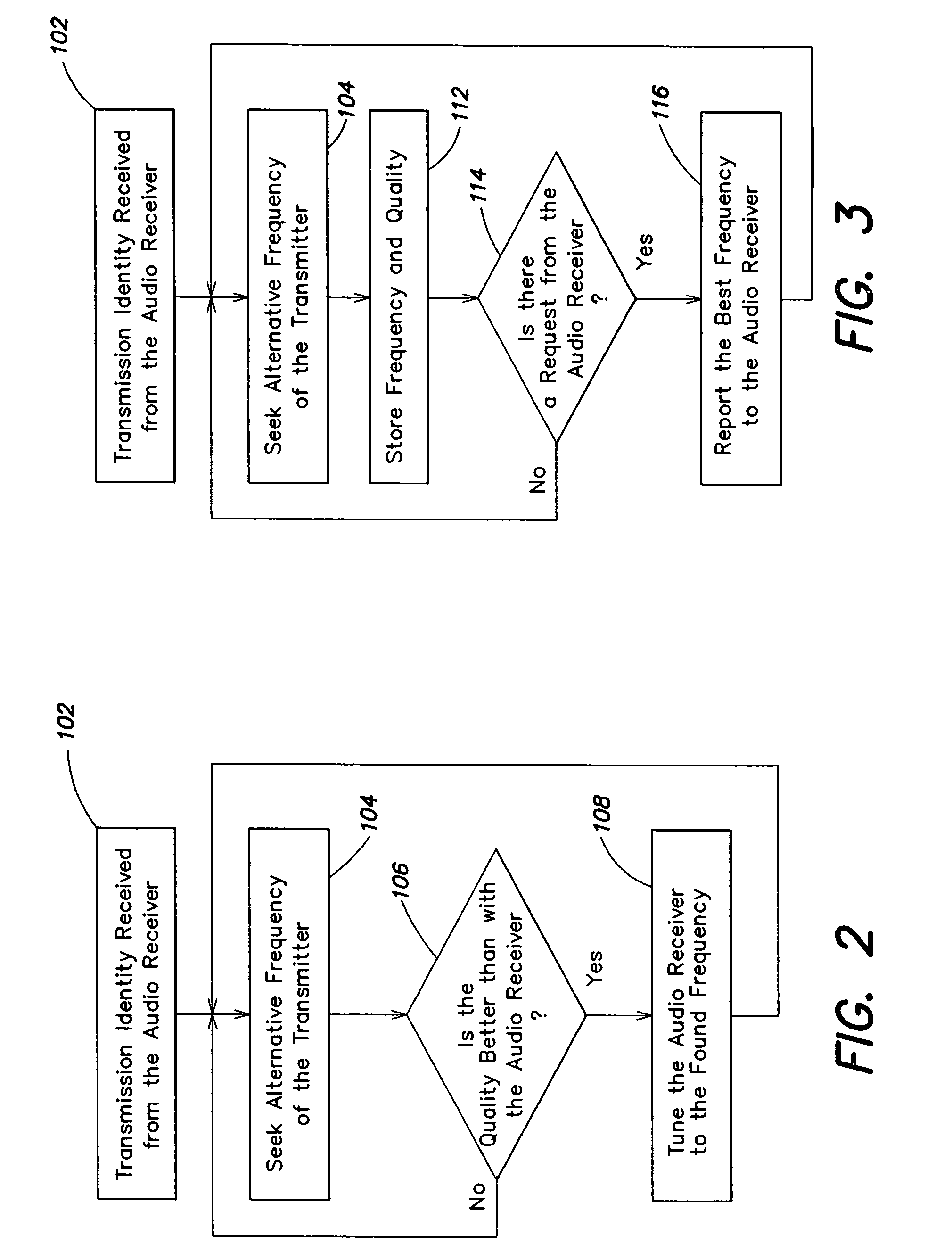
[0019]FIG. 1 illustrates a radio reception system 10 that includes at least two receivers, for example receivers 1a, 1b, 1c, 1d. The individual receivers are connected by a bus 2 (e.g., a MOST ring ). On this MOST ring 2, the individual receivers exchange information about the identity of a received transmitter and about reception qualities. An audio signal processing unit 3 is connected to the receiver 1a. This unit 3 amplifies and shapes the spectrum of the audio signal received from the receiver 1a, and provides an output signal to a loudspeaker (not shown). An external microcontroller 4 has input elements so that the user can input control instructions, for example to select a transmitter, regulate the tone, volume, and balance, etc. The microcontroller 4 is connected to the audio signal processing unit 3 and to the receiver 1a. The receiver 1a forwards instructions received from the microcontroller 4 to the MOST ring 2, inasmuch as these instructions concern any of the remainin...


PUM


Abstract

A method and apparatus for operating a radio reception system, which comprises a plurality of receivers assigned to a common output device, in which one of the receivers is designated as audio receiver and is tuned to a frequency of a radio transmitter, and outputs a signal received from the transmitter to the output device. At least one second receiver is designated as search receiver, and continuously searches its own reception frequency band for a frequency of the same transmitter. The system changes to a frequency of this transmitter, which was found by the search receiver, if the quality of the signal received by the audio receiver falls below a certain limit.

Description

[0001]This application is a continuation of Ser. No. 09 / 905,649 filed Jul. 13, 2001 now U.S. Pat. No. 7,120,404.BACKGROUND OF THE INVENTION[0002]The present invention relates to a radio receiving system, and in particular to a vehicle radio reception system that automatically remains tuned to the strongest frequency of a desired transmitter.[0003]Radio receivers with a so-called autobest functionality have been known for some time. These receivers, which are mainly used for car radios, automatically seeks another frequency of the same transmitter and tunes to this frequency, when the reception quality of a transmitter to which they are tuned falls below a certain limit. Even when a driver travels over large distances, which exceed the range of an individual USW broadcast station, he is thus able to continue listening to a transmitter without having to manually seek an alternate frequency when reception on the presently set frequency becomes unsatisfactory.[0004]However, these receiv...

Claims


Application Information

Patent Timeline
Patent Type & Authority Patents(United States)
IPC IPC(8): H04B7/08
CPCH03J1/0083H04H20/26H04B1/082
Inventor GIERL, STEFAN
Owner AG BECKER & CO
Learn More