ACM panel retaining clip and self-adjusting coplanar panel mounting system

a technology of retaining clip and coplanar panel, which is applied in the field of u-shaped clips, can solve problems such as captivating adjacent panel members

Active Publication Date: 2010-07-13
ROEGGE STEPHEN +2
View PDF8 Cites 50 Cited by
  • Summary
  • Abstract
  • Description
  • Claims
  • Application Information

AI Technical Summary

Benefits of technology

[0020]The clip installation is completed by passing the self-drilling screw through the hole in the base of the clip and screwing it into the extruded frame member. As each screw is rotated, it progresses downwardly until the countersink edges beneath the head of the screw comes in contact with the mated chamfered edge of the novel extruded clip. Further rotation of the screw causes the arms of the clip to separate and spread apart, thereby forcing the tips of the arms to symmetrically imbed into the edge of the panel members, which results in captivating the adjacent panel members.

Problems solved by technology

Further rotation of the screw causes the arms of the clip to separate and spread apart, thereby forcing the tips of the arms to symmetrically imbed into the edge of the panel members, which results in captivating the adjacent panel members.

Method used


Image

  • ACM panel retaining clip and self-adjusting coplanar panel mounting system
  • ACM panel retaining clip and self-adjusting coplanar panel mounting system
  • ACM panel retaining clip and self-adjusting coplanar panel mounting system

Examples


first embodiment

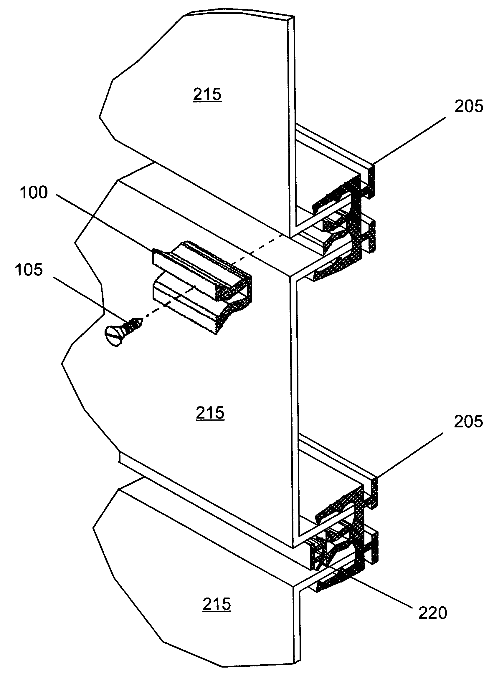
[0052]Turning now to FIG. 6, there is shown is a transverse sectional view of the narrow slot frame member 225, without pedestal spacers. The frame member 225 is comprised of the base 230 and having two upright arms 235, each arm orthogonal to the base 230 forming a U-shaped member. The collective cavity 245 of the narrow frame member 225 is designed to receive the edge members of two adjacent panels 215, slidably fit, and separated by a narrow slot opening, preferably 0.500 inches, between panels 215, into which the novel extruded clips 100 may be inserted.

second embodiment

[0053]In the present invention, FIG. 7 depicts a transverse sectional view of a narrow slot frame member 250 having a pair of pedestal spacers 255, to provide for the separation of the frame 205 from the hard mounting surfaces and to prevent the frame from contacting a hard surface such as cement, brick or block which may lie behind the frame member.

third embodiment

[0054]the present invention is shown in FIG. 8 where the wide slot frame member 260, without pedestal spacers, permits the frame 205 of the aluminum composite cladding system 200 to be mounted directly to a building wall or mounted using wood fining strips to provide a surface into which the mounting screws can penetrate.

[0055]The frame member 260 is comprised of base 230 and having two upright arms 235, each arm orthogonal to the base 230 forming a U-shaped frame member. The collective cavity 245 of the wide frame member 260 is designed to receive the edges of two adjacent panels 215, slidably fit, and separated by a wide slotted opening, preferably 0.750 inches between panels 215, into which the novel extruded clips 100 may be inserted.


PUM


Abstract

The present invention provides for a self-leveling structural element in a non-progressive attachment system, a U-shaped retentive clip having a base and two upwardly extending arms that are forced apart by the installation of a self-drilling screw, the novel retentive clip with screw coacting with an extruded frame to mount and retain a plurality of aluminum composite material (ACM) panels in a coplanar manner, to form an Aluminum Composite Cladding System; thereby comprising a non-progressive system that enables removal of individual panels for replacement or repair.

Description

CLAIM FOR BENEFIT OF PREVIOUSLY FILED APPLICATIONS[0001]Applicant's claim the benefit of Provisional Patent Application identified by Ser. No. 60 / 666,774, filed Mar. 31, 2005.FIELD OF INVENTION[0002]The present invention relates primarily to an extruded clip, and more particularly to a U-shaped clip for the retention of aluminum composite material (ACM) panels, wherein the clip is deformable for the mounting and retention of adjacent panels to obtain a smooth coplanar facing.BACKGROUND OF THE INVENTION[0003]The use of aluminum clad panels for exterior, building facings has been known in the prior art for some period of time.[0004]Aluminum Composite Cladding Systems are generally comprised of Aluminum Composite Material (ACM) panels, where panel flatness and a high performance finish are essential. Made from two sheets of aluminum bonded to a thermoplastic core, ACM is strong yet lightweight and with the right product knowledge and equipment, can be fabricated into components and sys...

Claims


Application Information

Patent Timeline
Patent Type & Authority Patents(United States)
IPC IPC(8): E04H1/00
CPCE04F13/0814E04F13/0889E04F13/12
Inventor ROEGGE, STEPHENDESANTIS, PETERMCINTYRE, J. ANDREW
Owner ROEGGE STEPHEN
Why Eureka
Try Eureka