Automatic transmission assembly for a vehicle, and vehicle incorporating same

a technology of automatic transmission and power unit, which is applied in mechanical equipment, transportation and packaging, and gear shifting, etc., can solve the problem of not addressing the shortening of the gear shifting time for downshifting, and achieve the effect of shortening the gear shifting time, and reducing the angular speed of the shift drum

Active Publication Date: 2010-07-13
HONDA MOTOR CO LTD
View PDF9 Cites 19 Cited by
  • Summary
  • Abstract
  • Description
  • Claims
  • Application Information

AI Technical Summary

Benefits of technology

[0017]According to the first aspect, when the upshifting command is output by the controller, the first clutch or the second clutch is engaged simultaneously with the upshifting command. Therefore, the clutch is engaged at the earliest timing when the preliminary upshifting action can be started, and hence the upshifting time is shortened.
[0029]Therefore, it is possible to perform various modes of shift drum actuation control corresponding to the partly neutral position, and the aim of shift drum actuation control for shortening a gear shifting time and reducing gear shifting shocks can reliably be achieved.

Problems solved by technology

However, the transmission assembly disclosed in Japanese Laid-Open Patent document No. 2006-52748 is aimed at shortening the gear shifting time for upshifting only, and does not address shortening a gear shifting time for downshifting.
However, the Japanese Patent No. 3325843 does not address a transmission having a partially neutral position intermediate between given angular positions corresponding to respective gear positions for temporarily reducing the angular speed of a shift drum upon gear shifting, and does not consider detecting a partially neutral position and performing corresponding gear shifting control.

Method used


Image

  • Automatic transmission assembly for a vehicle, and vehicle incorporating same
  • Automatic transmission assembly for a vehicle, and vehicle incorporating same
  • Automatic transmission assembly for a vehicle, and vehicle incorporating same

Examples


Embodiment Construction

[0057]It should be understood that only structures considered necessary for illustrating selected embodiments of the present invention are described herein. Other conventional structures, and those of ancillary and auxiliary components of the system, will be known and understood by those skilled in the art.

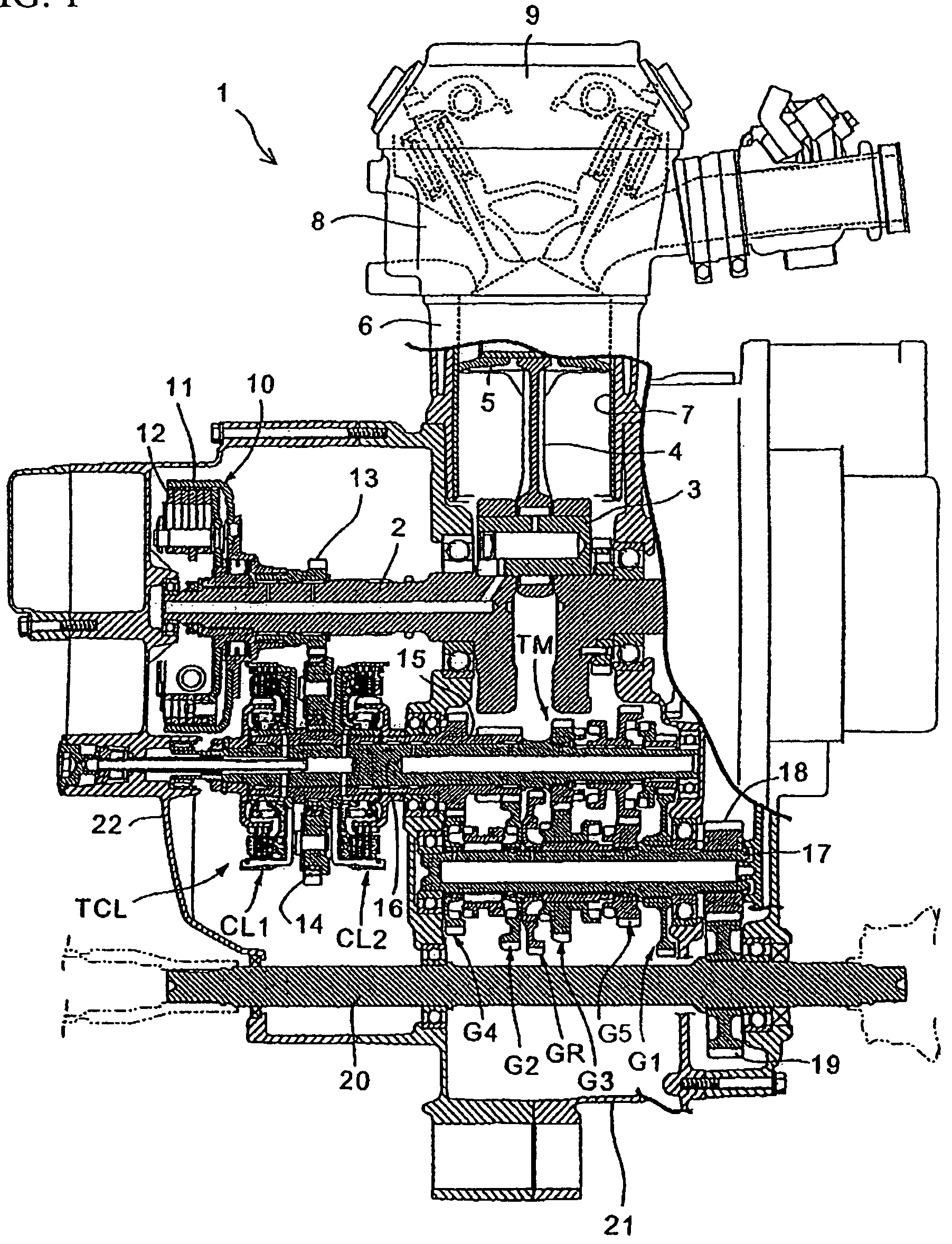
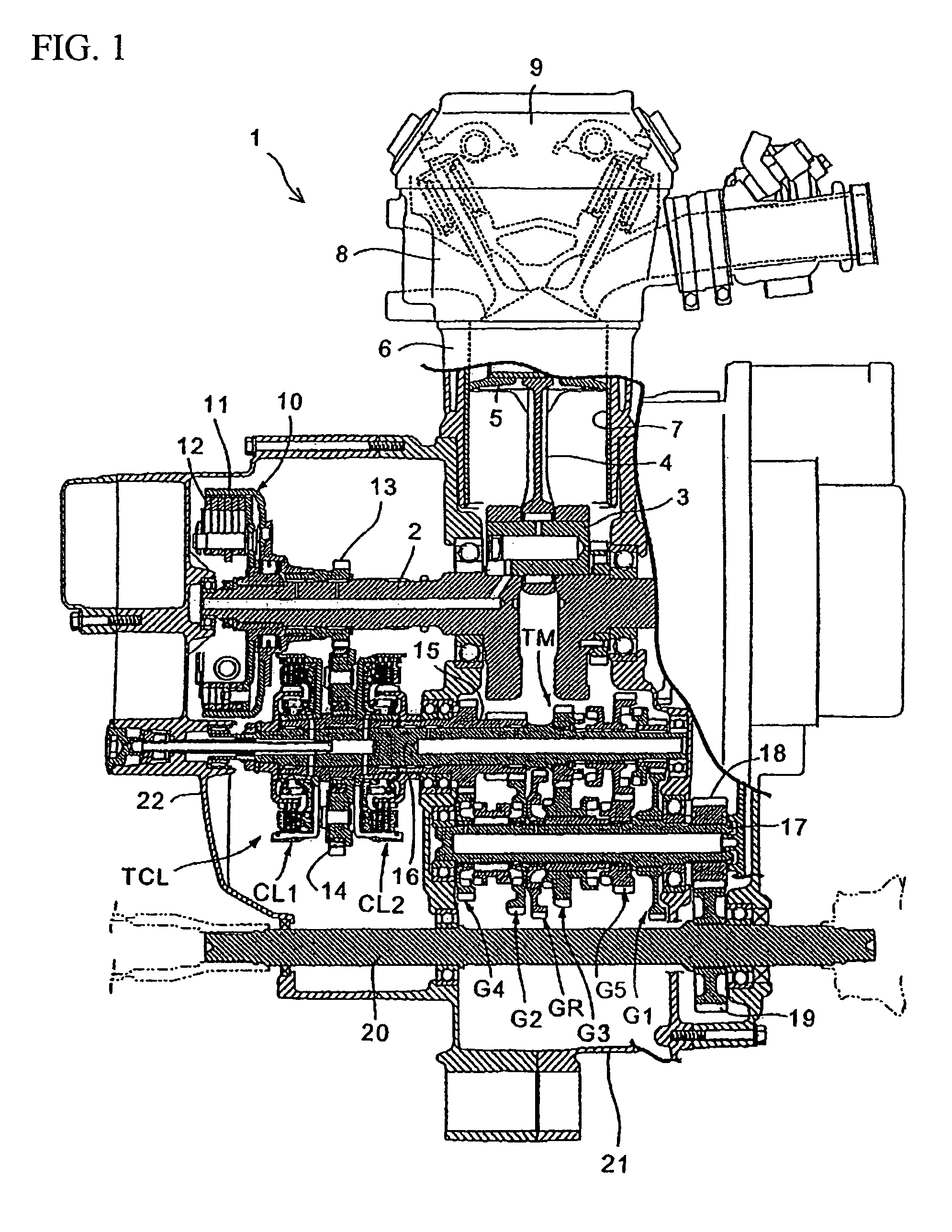
[0058]Illustrative embodiments of the present invention are described in detail below with reference to the drawings. FIG. 1 is a cross-sectional view of an engine 1 to which an automatic transmission assembly according to an illustrative embodiment of the present invention is applied.

[0059]The engine 1, used as a power source of a vehicle such as a riding-type four-wheeled vehicle (e.g., a car, a all-terrain vehicle), is a four-cycle single-cylinder internal combustion engine integrally combined with an automatic transmission assembly having an automatic transmission unit TM with five forward gear positions and a single reverse gear position. FIG. 19 shows a vehicle V (e.g. an AT...


PUM


Abstract

An automatic transmission assembly having a transmission unit including a plurality of gear pairs, a shift drum, a pair of clutches; and a controller. The controller performs a preliminary upshifting action in advance for angularly moving the shift drum depending on a next gear position in an upshifting direction while rotary drive power is being maintained at a given gear position, and when an upshifting command is output, the controller engages one of the clutches simultaneously with the command. When a downshifting command is output, the controller performs a preliminary downshifting action in advance based on the downshifting command. The partially neutral positions are provided between predetermined angular positions on the shift drum for temporarily reducing the angular speed of the shift drum when the shift drum is being angularly rotated.

Description

CROSS-REFERENCE TO RELATED APPLICATIONS[0001]The present application claims priority under 35 USC §119 based on Japanese patent applications Nos. 2007-056275 and 2007-056274, both filed on Mar. 6, 2007. The entire subject matter of each of these priority documents is incorporated by reference herein.BACKGROUND OF THE INVENTION[0002]1. Field of the Invention[0003]The present invention relates to an automatic transmission assembly for a power unit of a vehicle. More particularly, the present invention relates to an automatic transmission assembly configured and arranged for shortening a gear shifting time in both upshifting and downshifting of gears, and for controlling gear shifting for a partially neutral position on a shift drum of the automatic transmission assembly.[0004]2. Description of the Background Art[0005]There are a number of known automatic transmissions assemblies having a twin clutch assembly including two clutches (a first clutch and a second clutch) disposed between ...

Claims


Application Information

Patent Timeline
Patent Type & Authority Patents(United States)
IPC IPC(8): F16H59/00B60W10/10B60W30/18
CPCB60W10/02B60W10/113B60W30/19F16H61/688F16H63/18F16H61/32B60W2300/185F16H3/006F16H59/70Y10T477/638F16H2306/18Y10T74/19279Y10T477/26
Inventor KOBAYASHI, MASAKIHAMAOKA, SEIJIMIZUNO, KINYAKITTAKA, EIJIFUNAYOSE, YUSUKESAKAGUCHI, KAZUHIKOTANAKA, HIROSHI
Owner HONDA MOTOR CO LTD
Why Eureka
Try Eureka