Fletching system and method therefor

a technology of fletching and jigs, applied in the field of archery, can solve the problems of affecting the proper function affecting the accuracy of the fletching member, and consuming time, and achieving the effect of ensuring accuracy, ensuring accuracy, and avoiding bending

Inactive Publication Date: 2010-07-20
MARSHALL JOHN
View PDF16 Cites 20 Cited by
  • Summary
  • Abstract
  • Description
  • Claims
  • Application Information

AI Technical Summary

Benefits of technology

[0019]Accordingly, a feature and advantage of the present invention is its ability to quickly, accurately, easily, and removably attach a fletching member to an arrow shaft.
[0020]Another feature and advantage of the present invention is its ability to allow for replacement of a damaged fletching member.
[0021]Yet another feature and advantage of the present invention is ability to enable an unskilled fletcher to properly attach a fletching member to an arrow shaft.
[0022]Another feature and advantage of the present invention is its ability to protect a portion of the fletching member attached to the arrow shaft from damage during use or transportation.
[0023]Another feature and advantage of the present invention is its ability to allow for spiral or helical arrangement of a fletching member.

Problems solved by technology

Unfortunately, the process of applying the fletching members using conventional jigs is tedious, difficult, time-consuming, and does not ensure accurate results.
For example, one or more fletching members may become misaligned, and / or excess adhesive may flow out from between a fletching member and the arrow shaft, making a mess and potentially interfering with the proper function of the fletching members.
In addition, the jig is an expensive piece of specialized equipment and can only be used to apply fletching members to a single arrow shaft at a time.
Since the jig must remain attached to the arrow shaft until the adhesive cures, fletching techniques using a conventional jig are limited in their efficiency.
Thus, fletching using a conventional jig typically takes a long time and is done well in advance of the time when the arrow is to be fired.
This means that arrows are typically transported with the fletching members attached, whereby the fletching members may be damaged or become detached from the arrow shaft, thereby necessitating time-consuming repair.
Finally, conventional fletching techniques cannot practically be performed in the field in the event that a fletching member is damaged during use or transportation, due to inconvenience of carrying the jig, as well as the long curing time associated with the use of adhesive.

Method used


Image

  • Fletching system and method therefor
  • Fletching system and method therefor
  • Fletching system and method therefor

Examples


Embodiment Construction

[0033]In describing preferred embodiments of the present invention illustrated in the Figures, specific terminology is employed for the sake of clarity. The invention, however, is not intended to be limited to the specific terminology so selected, and it is to be understood that each specific element includes all technical equivalents that operate in a similar manner to accomplish a similar purpose.

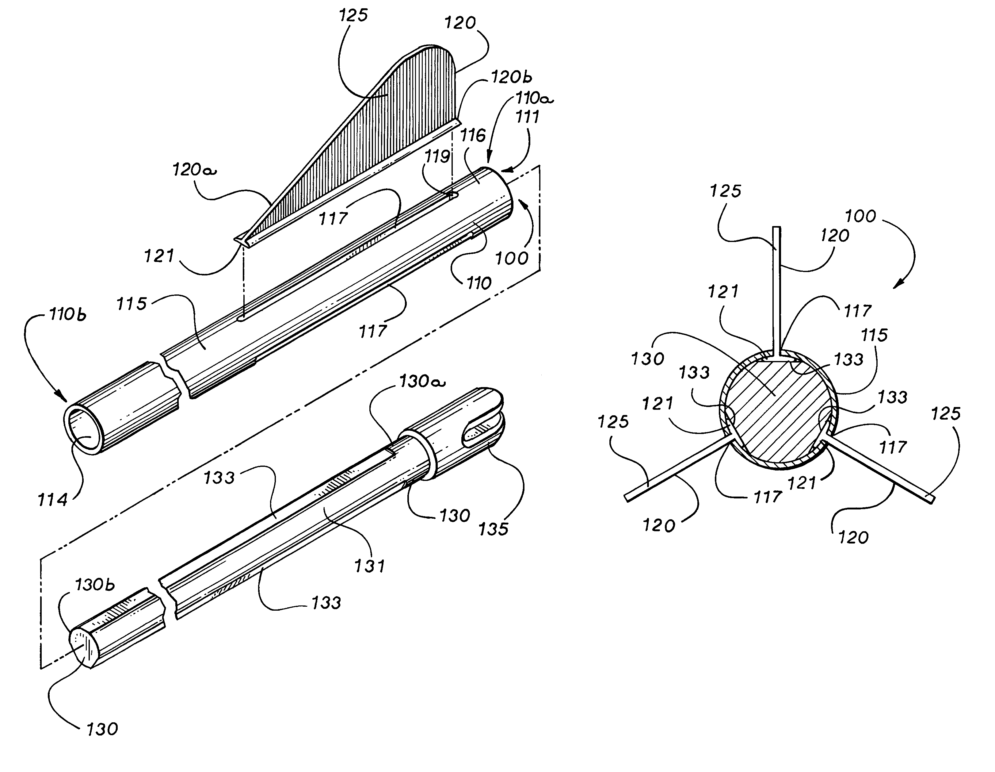
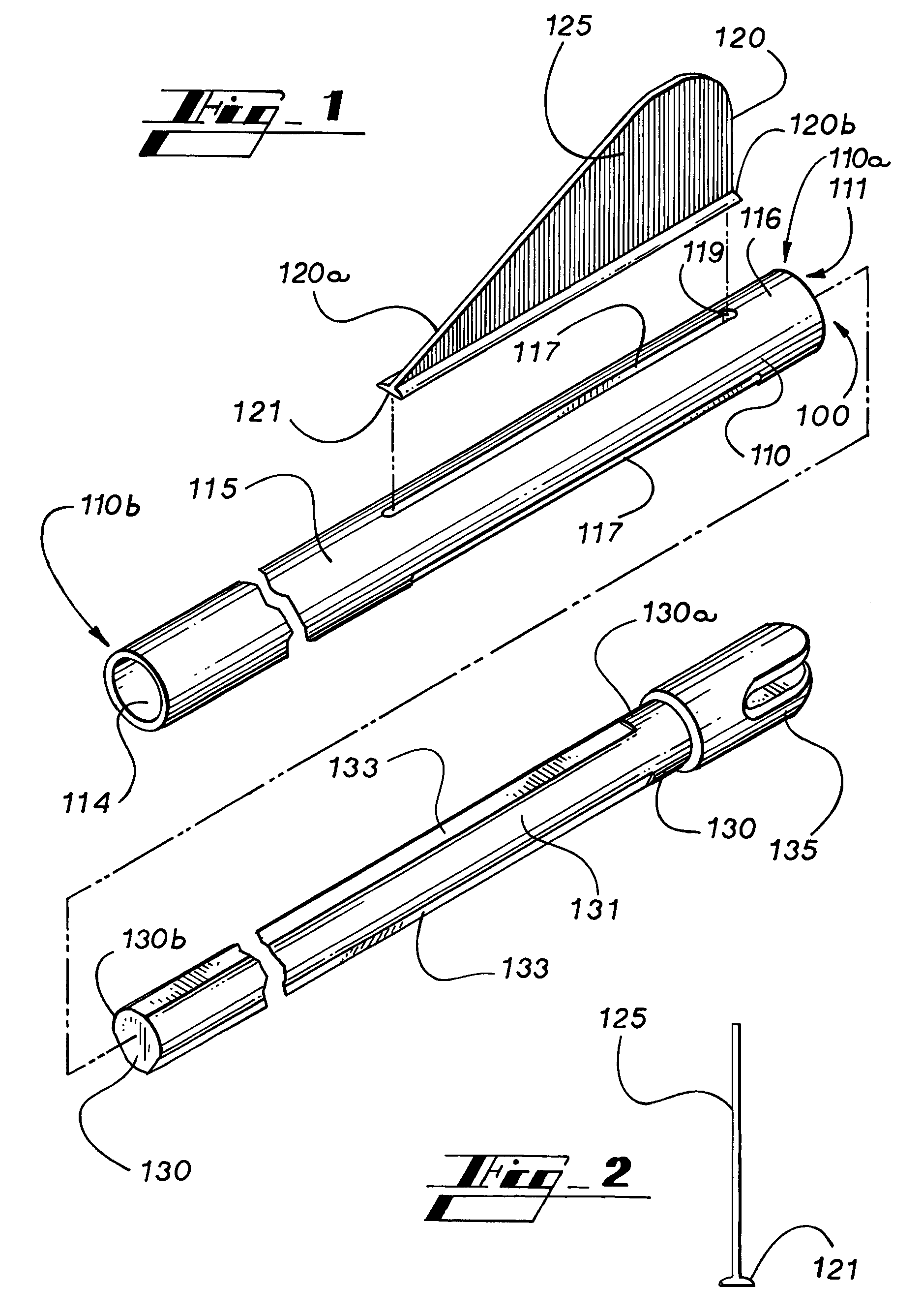
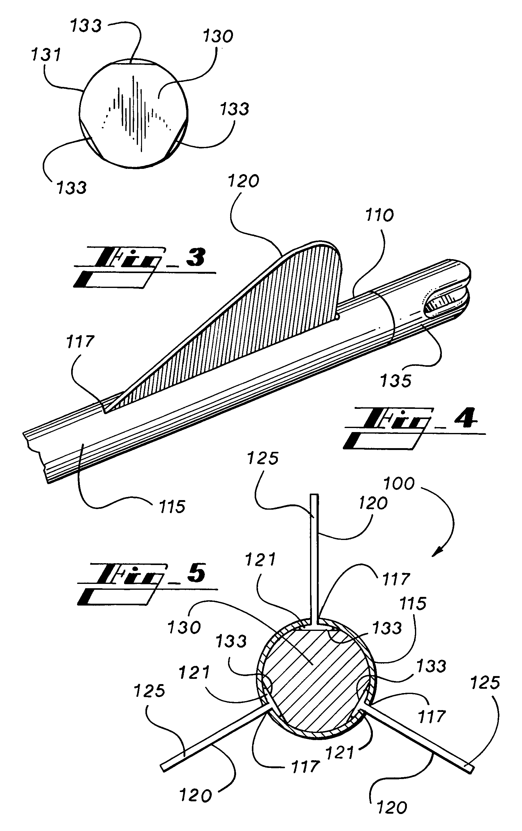
[0034]In that form of the preferred embodiment of the present invention chosen for purposes of illustration, FIG. 1 shows fletching system 100, preferably including arrow shaft 110, at least one fletching member 120, and plug member 130. Arrow shaft 110 preferably comprises an archery arrow shaft generally formed as a hollow circular cylinder. Arrow shaft 110 is preferably formed from aluminum, carbon, or a combination thereof, although arrow shaft 110 may be formed of wood, plastic, graphite, composite, or other suitable material or combinations thereof.

[0035]Arrow shaft 110 preferably c...


PUM


Abstract

A fletching system and method that allows for quick and easy attachment of a fletching member to an arrow shaft provides a slotted arrow shaft adapted to receive a fletching member projecting therethrough and an internal plug member disposed within a hollow center of the arrow shaft in pressing friction fit engagement with a flanged base portion of the fletching member wherein the flanged base portion is secured between the plug member and an internal surface of a sidewall of the arrow shaft.

Description

TECHNICAL FIELD[0001]The present invention relates generally to archery, and more specifically, to a fletching system and method.BACKGROUND OF THE INVENTION[0002]Bows and arrows have long been used in many various fields of endeavor, such as combat, hunting, sport, competition, and recreation. In almost all instances, accuracy is critical in achieving a successful shot. Most notably, flight characteristics of the arrow play a large role is in determining the accuracy of the shot. In order to adjust the flight characteristics of an arrow, one or more fletching member is typically provided on the shaft of an arrow. The design and attachment of the fletching members affect drag, spin, and trueness of flight, in addition to other flight characteristics.[0003]Typically, fletching members are attached to the outside of an arrow shaft using an adhesive. Correct alignment and positioning of the fletching members during attachment is usually attempted by using a fletching jig that retains th...

Claims


Application Information

Patent Timeline
Patent Type & Authority Patents(United States)
IPC IPC(8): F42B6/06
CPCF42B6/06
Inventor MARSHALL, JOHN
Owner MARSHALL JOHN
Why Eureka
Try Eureka