Base for power module

a power module and base technology, applied in the direction of power cables, lighting and heating apparatus, cables, etc., can solve the problems of warpage of heat radiation substrates, inability to accurately attach various components to heat radiation substrates, and inability to seal the resin casing in a sealed condition without forming a clearance, etc., to achieve accurate attachment, accurate attachment, and high rigidity

Inactive Publication Date: 2012-01-24
TOYOTA IND CORP +1
View PDF16 Cites 19 Cited by
  • Summary
  • Abstract
  • Description
  • Claims
  • Application Information

AI Technical Summary

Benefits of technology

[0028]According to the power module base of par. 1), the following advantageous effects are attained. In the case where the joining of the insulating substrate, the heat radiation substrate, the heat radiation fin, and the component attachment plate is performed by, for example, brazing, the insulating substrate, the heat radiation substrate, and the component attachment plate thermally expand at the time of heating for brazing, and are brazed together in a thermally expanded state. Subsequently, the insulating substrate, the heat radiation substrate, and the component attachment plate thermally contract after completion of the heating. Since the heat radiation substrate is formed of a high-thermal-conduction material such as aluminum and its linear expansion coefficient is larger than that of the insulating substrate, the degree of thermal expansion of the heat radiation substrate is greater than that of the insulating substrate, and, as a result, the degree of thermal contraction of the heat radiation substrate is greater than that of the insulating substrate. Therefore, when the insulating substrate and the heat radiation substrate thermally contract as a result of being cooled to room temperature after completion of brazing, the degree of contraction of the heat radiation substrate becomes larger than that of the insulating substrate, and the heat radiation substrate is pulled by the insulating substrate, so that deformation such as warpage arises in the heat radiation substrate. However, since the component attachment plate is thicker than the heat radiation substrate and is high in rigidity, the component attachment plate is not affected by the deformation of the heat radiation substrate, and the surface of the component attachment plate opposite the surface joined to the heat radiation substrate is maintained flat. Accordingly, various components can be accurately attached. For example, when a casing for covering a power device and the insulating substrate of the power module base is attached to the component attachment plate, no clearance is formed between the casing and the component attachment plate, and the interior of the casing can be maintained in a sealed condition. Further, an electrical wiring frame and components necessary for the power module, such as electronic components, can be accurately attached.
[0029]In addition, unlike the power module base disclosed in Patent Document 1, the thickness of the heat radiation substrate is not required to increase. Therefore, a heat conduction path from the power device to the heat radiation fin becomes relatively short, whereby a drop in heat radiation performance is suppressed.
[0030]According to the power module base of par. 2), heat generated from the power device mounted on the insulating substrate is conducted to the heat radiation fin via the insulating substrate and the heat radiation substrate, and is radiated from the heat radiation fin to a cooling liquid flowing within the cooling jacket. Accordingly, a relatively excellent heat radiation performance is attained.
[0031]In the case where the insulating substrate and the heat radiation substrate are brazed together, the heat radiation substrate and the heat radiation fin are brazed together, and the heat radiation substrate and the component attachment plate are brazed together as in the power module base of par. 3), the insulating substrate, the heat radiation substrate, and the component attachment plate thermally expand at the time of heating for brazing, and are brazed together in a thermally expanded state. Subsequently, the insulating substrate, the heat radiation substrate, and the component attachment plate thermally contract after completion of the heating. Since the heat radiation substrate is formed of a high-thermal-conduction material such as aluminum and its linear expansion coefficient is larger than that of the insulating substrate, the degree of thermal expansion of the heat radiation substrate is greater than that of the insulating substrate, and, as a result, the degree of thermal contraction of the heat radiation substrate is greater than that of the insulating substrate. Therefore, when the insulating substrate and the heat radiation substrate thermally contract as a result of being cooled to room temperature after completion of brazing, the degree of contraction of the heat radiation substrate becomes larger than that of the insulating substrate, and the heat radiation substrate is pulled by the insulating substrate, so that deformation such as warpage arises in the heat radiation substrate. However, since the component attachment plate is thicker than the heat radiation substrate and is high in rigidity, the component attachment plate is not affected by the deformation of the heat radiation substrate, and the surface of the component attachment plate opposite the surface joined to the heat radiation substrate is maintained flat. Accordingly, various components can be accurately attached. For example, when a casing for covering the power device and the insulating substrate of the power module base is attached to the component attachment plate, no clearance is formed between the casing and the component attachment plate, and the interior of the casing can be maintained in a sealed condition. Further, an electrical wiring frame and components necessary for the power module, such as electronic components, can be accurately attached.
[0032]According to the power module base of par. 4), a housing for accommodating the entire power module, an electrical wiring frame, and various components necessary for the power module can be attached by making use of the second component attachment plate. In addition, in the case where these components generate heat, these heat generating components can be cooled by a cooling liquid flowing through the cooling jacket.
[0033]According to the power module base of par. 6), heat conducting from the power device mounted on the insulating substrate is conducted to the heat radiation substrate while being dispersed in the direction of the plane of the heat transfer layer. Therefore, the heat conduction to the heat radiation substrate and thus to the heat radiation fin is improved.

Problems solved by technology

Therefore, if no measure is taken, when the insulating substrate, the heat radiation substrate, and the heat sink thermally contract as a result of being cooled to room temperature after completion of brazing, the degrees of contraction of the heat radiation substrate and the heat sink become greater than that of the insulating substrate, and the heat radiation substrate and the heat sink are pulled by the insulating substrate, so that deformation such as warpage arises in the heat radiation substrate.
As a result, it becomes impossible to accurately attach various components onto the heat radiation substrate.
For example, in the case of a resin casing for covering the insulating substrate and the power device, there is a possibility that the resin casing cannot be attached in a sealed condition without forming a clearance.
Further, there is a possibility that an electrical wiring frame and components necessary for the power module, such as electronic components, cannot be accurately attached.
However, if the thickness of the heat radiation substrate is increased, the heat conduction path from the power device to the heat sink increases in length, and heat radiation performance may drop.Patent Document 1: Japanese Patent Application Laid-Open (kokai) No. 2003-86744

Method used


Image

  • Base for power module
  • Base for power module
  • Base for power module

Examples


Embodiment Construction

[0035]Embodiments of the present invention will next be described with reference to the drawings. In the following description, the upper, lower, left-hand, and right-hand sides of FIG. 1 will be referred to as “upper,”“lower,”“left,” and “right,” respectively.

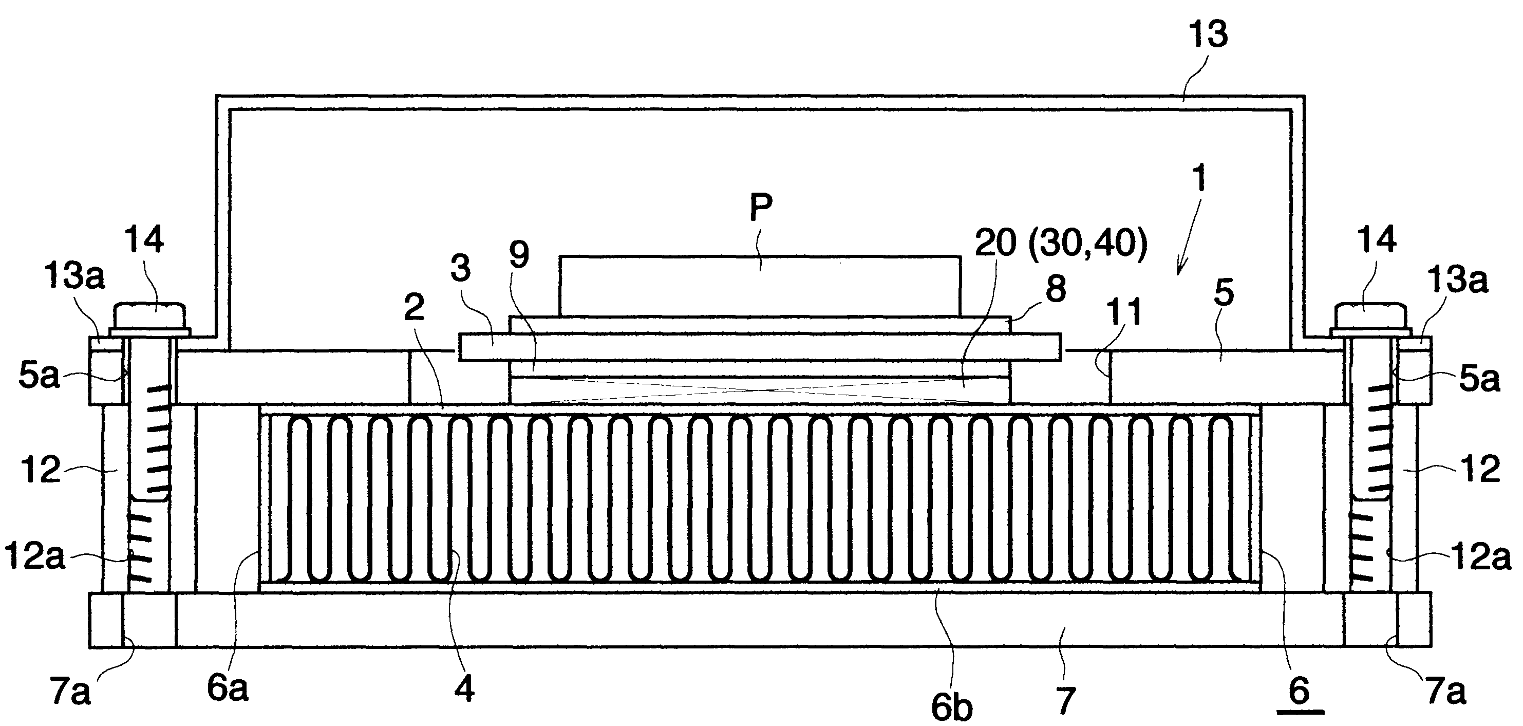
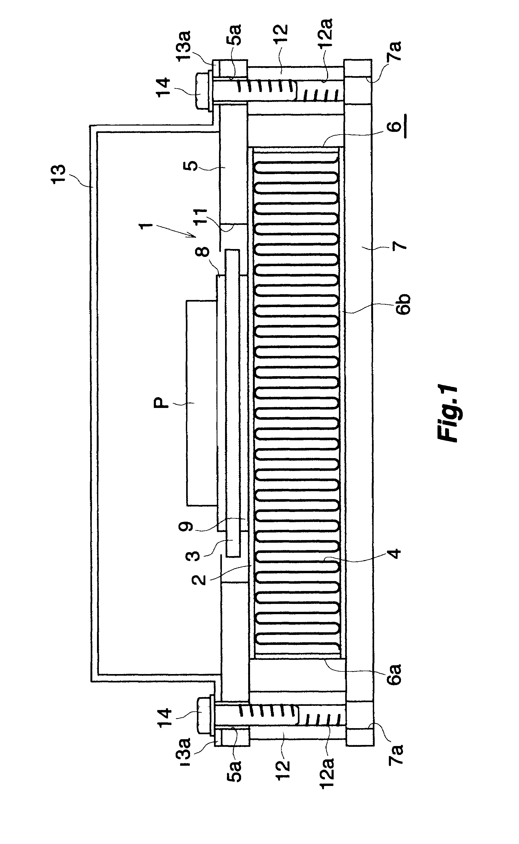
[0036]FIG. 1 shows the overall structure of a power module which uses a power module base according to the present invention.

[0037]In FIG. 1, the power module base (1) includes a heat radiation substrate (2); an insulating substrate (3) brazed to an upper surface of the heat radiation substrate (2); a heat radiation fin (4) brazed to a lower surface of the heat radiation substrate (2); an upper component attachment plate (5) brazed to a portion of the upper surface of the heat radiation substrate (2), the portion surrounding the insulating substrate (3); a cooling jacket (6) fixed to the lower surface of the heat radiation substrate (2) and covering the heat radiation fin (4); and a lower component attachment plate (7) (a seco...


PUM


Abstract

A power module base includes a heat radiation substrate formed of a high-thermal-conduction material, an insulating substrate joined to an upper surface of the heat radiation substrate, a wiring layer provided on an upper surface of the insulating substrate, and a heat radiation fin joined to a lower surface of the heat radiation substrate. A component attachment plate thicker than the heat radiation substrate and including a through hole for accommodating the insulating substrate is joined to the upper surface of the heat radiation substrate such that the insulating substrate is located within the through hole. This power module base can maintain the upper surface of the component attachment plate flat, and various components required for a power module, such as a casing, can be attached onto the component attachment plate.

Description

TECHNICAL FIELD[0001]The present invention relates to a base for a power module which partially constitutes a power module.[0002]The term “aluminum” as used herein and in the appended claims encompasses aluminum alloys in addition to pure aluminum, except for the case where “aluminum nitride,”“aluminum oxide,” or “pure aluminum” is specified. Further, the term “copper” as used herein and in the appended claims encompasses copper alloys in addition to pure copper.BACKGROUND ART[0003]In a power module which includes a power device formed of a semiconductor device, such as an IGBT (Insulated Gate Bipolar Transistor), the semiconductor device must be held at a predetermined temperature or lower by means of efficiently radiating heat generated therefrom. A base for a power module (hereinafter referred to as a “power module base”) which meets the requirement has conventionally been proposed (see Patent Document 1). The power module base includes a ceramic insulating substrate having an al...

Claims


Application Information

Patent Timeline
Patent Type & Authority Patents(United States)
IPC IPC(8): H05K7/20H01L23/34F28F7/00
CPCH01L23/4006H01L23/473H01L23/3677H01L23/3735H01L2924/0002H01L25/072H01L2924/00H01L23/36H01L23/40H01L25/07H01L25/18
Inventor TOH, KEIJIMORI, SHOGOOBARA, HIDEYASUWAKABAYASHI, NOBUHIRONAKAGAWA, SHINTAROYAMAUCHI, SHINOBU
Owner TOYOTA IND CORP
Why Eureka
Try Eureka