Implantable spinal fixation crosslink

a crosslink and spinal technology, applied in the field of implantable medical devices, can solve the problems of insufficient degree, inability to adjust or use surgeons in the surgical setting, and insufficient strength of art crosslinks, so as to simplify the effort of linking, improve the degree of strength, and ensure the effect of equal effectiveness

Inactive Publication Date: 2013-04-16
CROSSLINK MEDICAL LLC
View PDF29 Cites 20 Cited by
  • Summary
  • Abstract
  • Description
  • Claims
  • Application Information

AI Technical Summary

Benefits of technology

[0008]This tie rod fastener allows the head and neck of the tie rod to translate linearly relative to the housing, as well as rotate an orientation of the housing relative to the tie rod in three different directions about three mutually perpendicular axes. Thus, the orientation of the housing relative to the tie rod when fastened to the tie rod is adjustable in one or more of four different ways to cause the housing and tie rod to attach together in precisely the orientation desired for the tie rod.
[0021]Another object of the present invention is to provide a crosslink which has a configuration which exhibits a high strength when formed of biocompatible materials such as stainless steel, titanium alloys, or high strength plastic or composite materials.

Problems solved by technology

These prior art crosslinks have been less than entirely adequate in that they either do not provide a high degree of adjustability to easily fit all potential different spine rod relative orientations, or they are not easily adjusted or used by the surgeons in the surgical setting.
In some instances a surgeon will even choose not to utilize any crosslink because known crosslinks have been too difficult to fix in place or provide insufficient additional stability to the overall spinal fixation implant to warrant the difficulty associated with their implantation.
Furthermore, the spine itself can interfere with the crosslink by blocking a straight path between the two rods, making many such prior art crosslinks unable to fit as desired.

Method used


Image

  • Implantable spinal fixation crosslink
  • Implantable spinal fixation crosslink
  • Implantable spinal fixation crosslink

Examples


Embodiment Construction

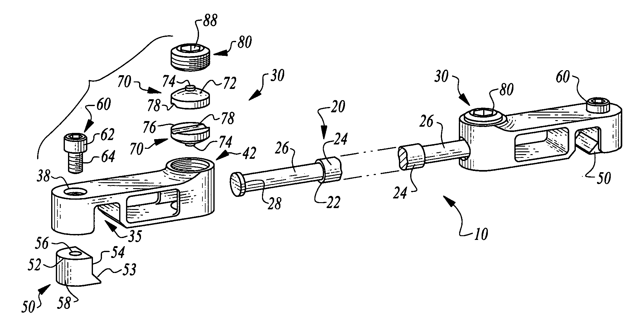
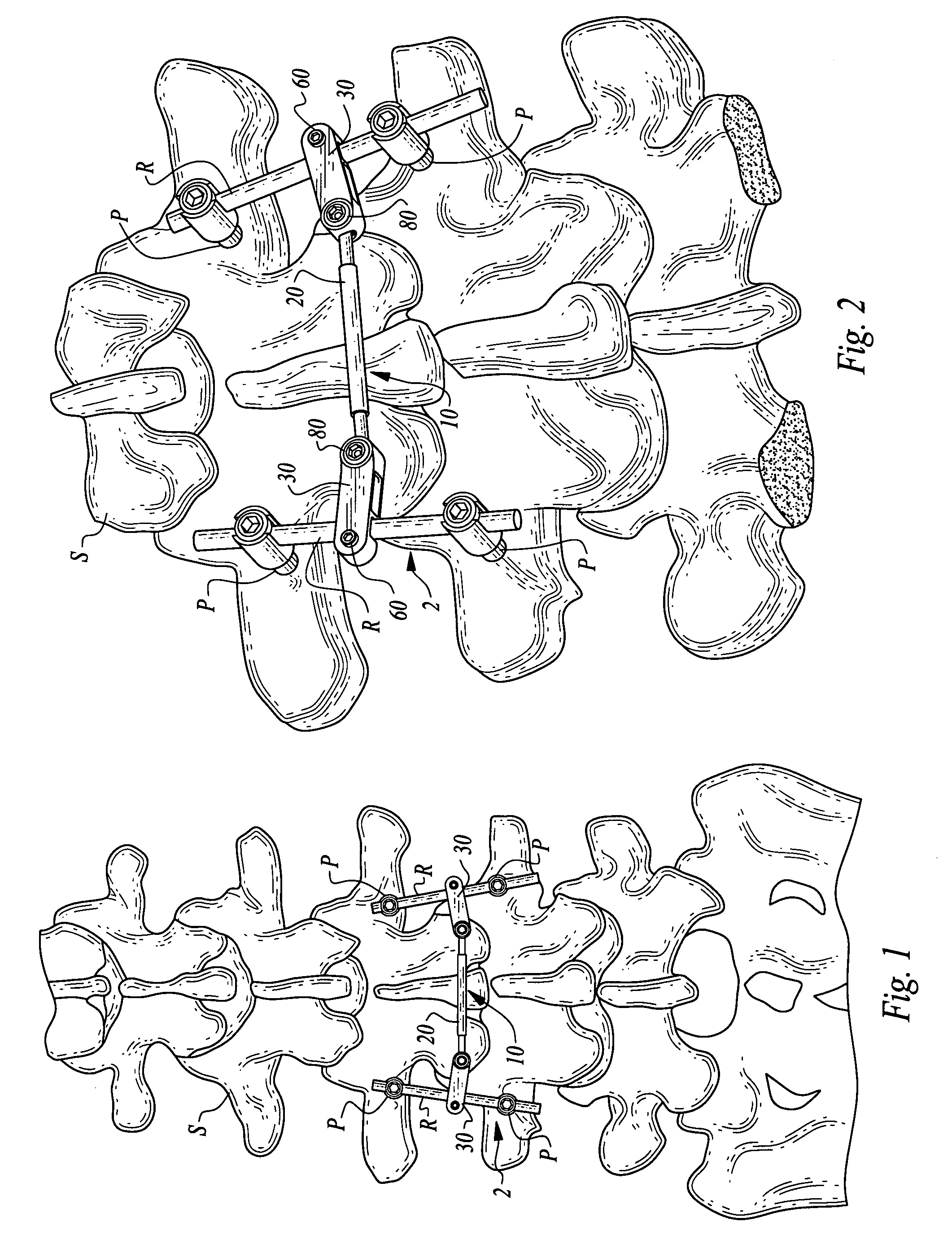
[0039]Referring to the drawings, wherein like reference numerals represent like parts throughout the various drawing figures, reference numeral 10 is directed to a crosslink for joining two spinal fixation assemblies 2 (FIGS. 1 and 2) on either side of a spine S. The fixation assemblies 2 generally include a spine rod R rigidly joined to the spine S through pedicle screws P or other attachment mechanisms. The spine rods R thus provide support for the spine S to help the spine S to support longitudinal loads experienced by the spine S. The crosslink 10 is rigidly coupleable to each of the spine rods R and spanning the spine S laterally, to rigidly join the two rods R and thus the two fixation assemblies 2 securely together.

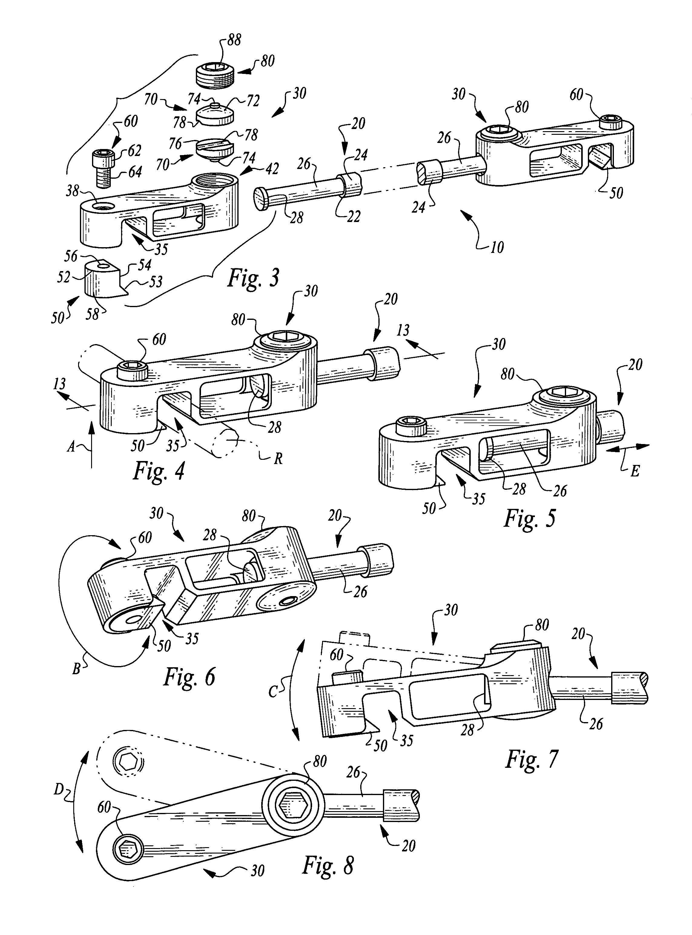
[0040]In essence, and with particular reference to FIGS. 1-3 and 16, basic details of the crosslink 10 are described, according to a preferred embodiment. The crosslink 10 includes an elongate tie rod 20 and a pair of housings 30, with one housing 30 on each end of...


PUM


Abstract

A crosslink is provided for joining two spine rods. The crosslink includes an elongate tie rod and a pair of housings at each end of the tie rod. The housings are preferably identical and have independent fasteners including a spine rod fastener and a tie rod fastener for connecting each housing to one of the spine rods and fixation of the tie rod. The tie rod fasteners include a pair of hemisphere clamps residing within a chamber in the housing which grip the tie rod therebetween to fix the tie rod to the clamp when a set screw applies a clamping force on the hemisphere clamps. The tie rod fastener is adjustable, so that both translation of the tie rod relative to the housings and rotation about three mutually perpendicular axes can be accommodated for orienting of the housings relative to the tie rod precisely where desired.

Description

FIELD OF THE INVENTION[0001]The following invention relates to implantable medical devices for coupling adjacent vertebrae of a spine together and strengthening and supporting the spine. More particularly, this invention relates to crosslinks for such implantable spinal fixation devices which generally include rods on opposite sides of the spine coupled through pedicle screws or other attachments directly to the vertebrae, with the crosslink securing the two rods to each other.BACKGROUND OF THE INVENTION[0002]For certain spine injuries, the use of an implantable spinal fixation device is indicated to join two or more vertebrae together. A common form of spinal fixation includes utilizing an elongate spinal rod oriented generally parallel to the spine and spaced laterally to one side of the spine. This rod is coupled to at least two vertebrae, and often more than two vertebrae, through various different fixation fasteners. One common form of fixation fastener is a pedicle screw which...

Claims


Application Information

Patent Timeline
Patent Type & Authority Patents(United States)
IPC IPC(8): A61B17/70
CPCA61B17/7052
Inventor POIRIER, DAVID A.ROVNER, ROBERT A.SHEVICK, BARRY L.
Owner CROSSLINK MEDICAL LLC
Why Eureka
Try Eureka