
Cap for use as hearing protection

a technology for hearing protection and caps, applied in the field of caps, can solve the problems of significant impairment of dampening of such noise, increased weight of protective caps, and increased thickness of caps, so as to avoid problems such as tool wear and reduced strength, the effect of increasing the thickness of the cap and increasing the sound attenuation

Active Publication Date: 2010-08-03
HONEYWELL SAFETY PROD USA INC
View PDF8 Cites 41 Cited by
  • Summary
  • Abstract
  • Description
  • Claims
  • Application Information

AI Technical Summary

Benefits of technology

The present invention provides a cap for hearing protection that improves sound attenuation compared to prior-art caps. The cap has weight elements that are positioned to block audio modes of vibration, which results in better sound attenuation at high frequencies. The use of weight elements avoids the need for metal in the cap, which can cause tool wear and reduced strength. The weight elements can be attached to the cap shell or the bottom plate, and their density can be higher or lower than that of the cap shell. The invention allows for thinner caps, lower material costs, and faster cooling times.

Problems solved by technology

However, noise at certain frequencies or in certain frequency ranges may create resonance phenomena in the caps of the hearing protection, which significantly impairs the dampening of such noise.
Increasing the thickness “outwards” gives the drawback that the hearing protection will be larger and more unwieldy.
Increasing the thickness “inwards” gives the drawback that the sound attenuation can even be impaired since the inner volume will be smaller, and a high degree of absorption requires not only weight but also a large inner volume of the cap—the relative variation in pressure of the air inside the cap will be smaller when the air volume is larger.
The possibility of increasing the weight in this manner is, however, limited since there is an upper limit of how much metal can be admixed to the plastic in view of tool wear, strength properties etc.
Furthermore an increase of the weight of the cap shell affects low frequency sound the most.
Thus there remains the problem of damping resonance at higher frequencies, i.e. above about 1 kHz.
Just like in U.S. Pat. No. 6,353,938 B1, it is thus shown how sound attenuation can be improved by an increased weight of cap shells, which has the greatest effect on low frequency sound, but no solution is provided to the problem of improving sound attenuation in the higher frequency range.

Method used


Image

  • Cap for use as hearing protection
  • Cap for use as hearing protection
  • Cap for use as hearing protection

Examples


Embodiment Construction

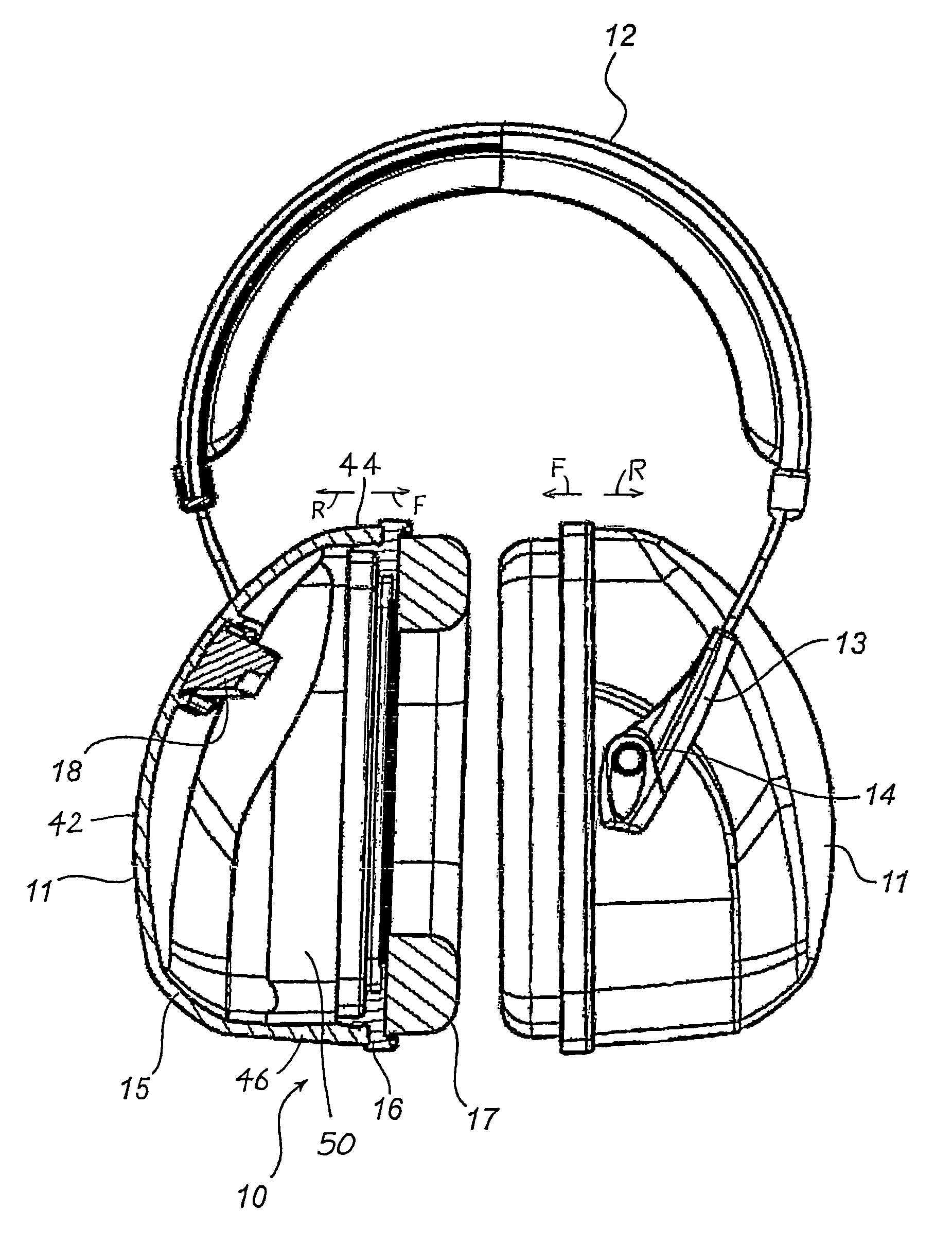
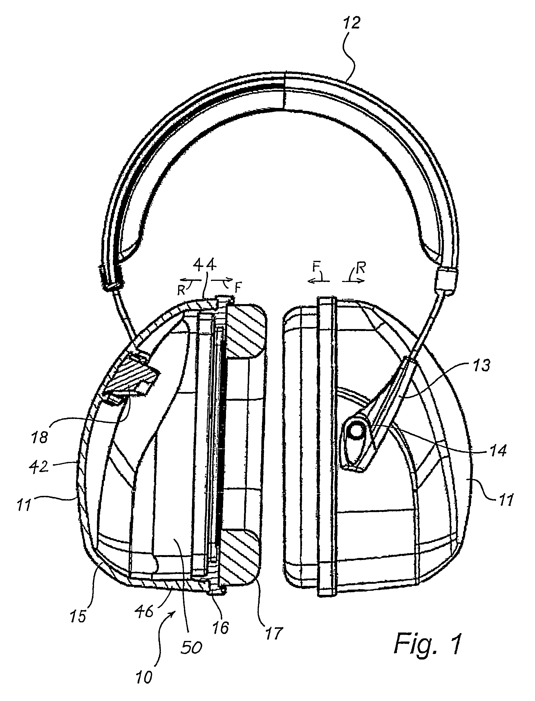
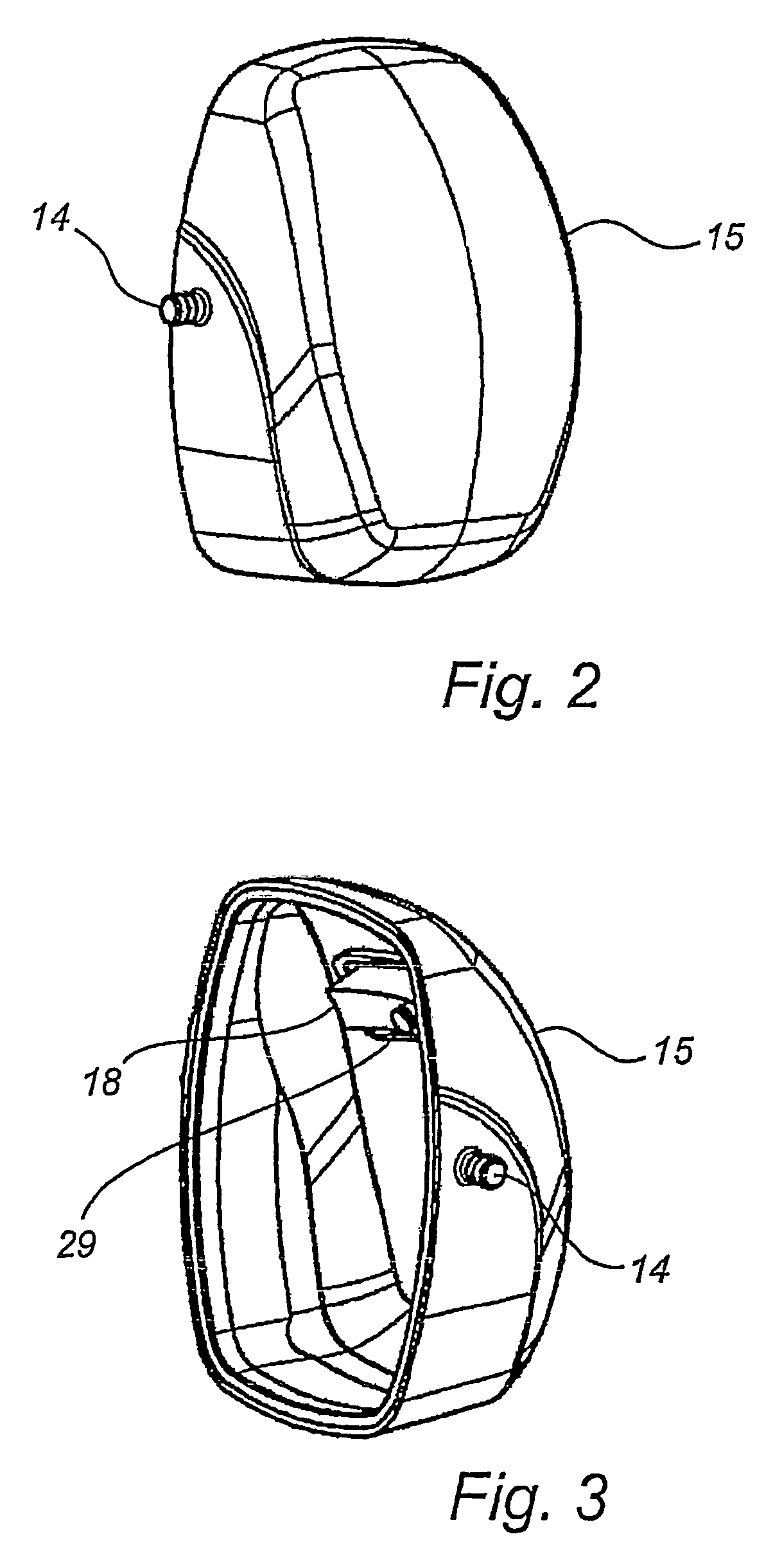
[0037]FIG. 1 illustrates a hearing protector 10 comprising a headband 12 to abut against a user's crown and an embodiment of a cap 11 according to the invention to be mounted at each end of the headband, thus enclosing an external ear of the user. Each cap 11 comprises a cap shell 15, an intermediate bottom plate 16 and a sealing ring 17 to seal against the head of the user. A sound absorbing material (not shown) is preferably arranged between the cap shell 15 and the bottom plate 16, for instance in the form of a pad of foam plastic. Each cap is mounted at an end of the headband 12 by suspension from pins 14 on opposite sides of the cap shell 15, which pins are inserted into corresponding holes of holders 13 at each end of the headband 12, so that the caps 11 are pivotally suspended from the headband 12.

[0038]Each cap has front F and rear R ends that lie respectively closest and furthest from the person's ear. Each cap shell 15 has a closed rear wall 42, closed top and bottom walls...


PUM


Abstract

The present invention relates to a cap (11) intended for use as hearing protection and adapted to enclosed the external ear of a user, characterized by at least one vibration-damping weight element (18, 38a-b) of the cap (11), which weight element is arranged so as to at least partly block an audio mode of vibration that would have existed in the cap in the absence of said weight element (18, 38a-b). The invention also relates to a method of producing such a cap, and use of the same.

Description

CROSS-REFERENCE[0001]This is a continuation-in-part of PCT / SE2005 / 000923 filed 16 Jun. 2005, which claimed priority from Swedish patent application 0401536-8 filed 16 Jun. 2004.FIELD OF THE INVENTION[0002]The present invention relates to a cap intended for use as hearing protection and adapted to enclose the external ear of a user. The invention also relates to a method of producing such a cap, and use of such a cap.BACKGROUND ART[0003]A common type of hearing protection comprises two caps which are connected by a headband. The headband is adapted to be placed over the head of the user and the two caps are adapted to be arranged one on each side of the user's head so as to enclose both external ears of the user. The cap in turn comprises a cap shell, which usually is made of plastic, a sealing ring, which is adapted to fit the head of the user, and some kind of sound-absorbing material arranged inside the cap. It is also common for a so-called bottom plate to be arranged, to which t...

Claims


Application Information

Patent Timeline
Patent Type & Authority Patents(United States)
IPC IPC(8): A42B1/06A61FA61F11/14
CPCA61F11/14
Inventor HANSSON, FREDRIKFRANZEN, PETERHISELIUS, PER
Owner HONEYWELL SAFETY PROD USA INC
Learn More