Silencer for an auxiliary power unit of an aircraft

a technology for auxiliary power units and aircraft, which is applied in the direction of liquid fuel engines, instruments, air-flow influencers, etc., and can solve problems such as complete decoupling

Active Publication Date: 2014-07-08
AIRBUS OPERATIONS GMBH
View PDF5 Cites 4 Cited by
  • Summary
  • Abstract
  • Description
  • Claims
  • Application Information

AI Technical Summary

Benefits of technology

[0007]An aspect of the invention proposes a silencer for an auxiliary power unit of an aircraft in which improved sound attenuation can be achieved without increasing the outer dimensions of the silencer. The silencer is as compact as possible while still providing effective sound attenuation in a wide frequency range.
[0011]In the design of such silencers, optimizing or maximizing energy transmission of slightly attenuated plane waves to form transversal waves that may be sound attenuated in a significantly better manner provides a challenge. In silencers optimized in this manner it may also occur that due to a resonance phenomenon a first radial mode in the silencer downstream of the auxiliary power unit is excited. The integration according to an embodiment of the invention of the central body may significantly reduce this effect. By adjusting the natural frequency of the inner cells formed in the central body to the first radial mode of a standing wave in the silencer a high flow speed through the wall material of the casing of the central body is caused so that, as a result of this, acoustic energy is reduced, as is excitation of the radial mode.
[0012]The silencer according to an embodiment of the invention attenuates exhaust gas noises of an auxiliary power unit significantly better than do conventional silencers for auxiliary power units, which silencers operate according to a similar principle with a porous flow channel and cells formed around the flow channel.
[0018]In an advantageous embodiment a perforated walling encloses the casing. As a result of the additional use of a perforated walling, independent setting of the flow resistance for acoustic absorption and the natural frequency of the inner cells can be achieved. If no perforated wall were to enclose the casing and if the flow resistance of the casing were to be increased in order to improve absorption, the natural frequency of the inner cells would decrease. The perforated walling can thus further improve the effectiveness of the silencer according to the invention.
[0023]In an advantageous embodiment the central body is connected to a turbine stator of the auxiliary power unit. In this manner a maximum extension of the silencer within the aircraft can be achieved while maintaining an otherwise unchanged provision of installation space.

Problems solved by technology

This results in complete decoupling while maintaining an unchanged installation space of the silencer.

Method used


Image

  • Silencer for an auxiliary power unit of an aircraft
  • Silencer for an auxiliary power unit of an aircraft
  • Silencer for an auxiliary power unit of an aircraft

Examples


Embodiment Construction

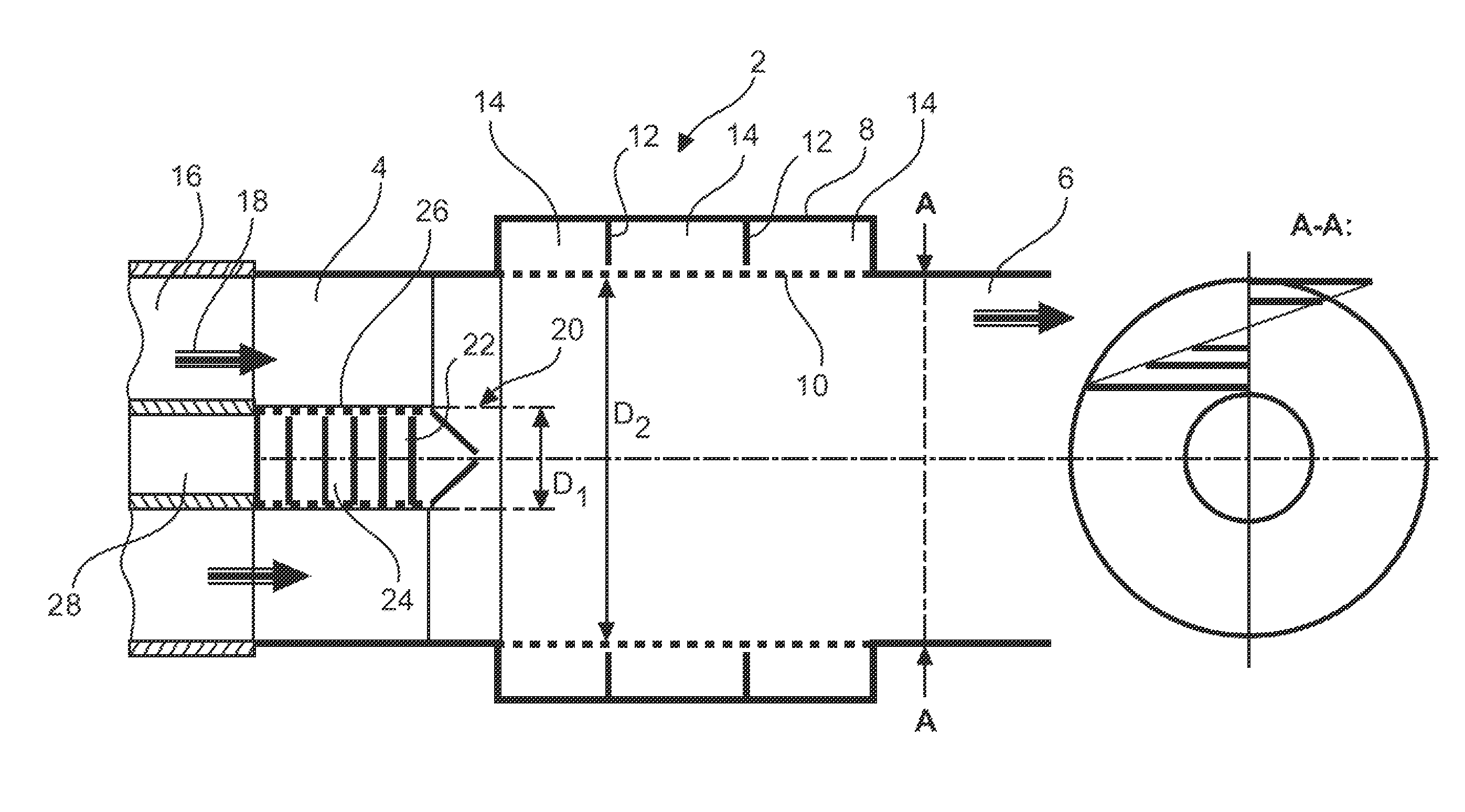
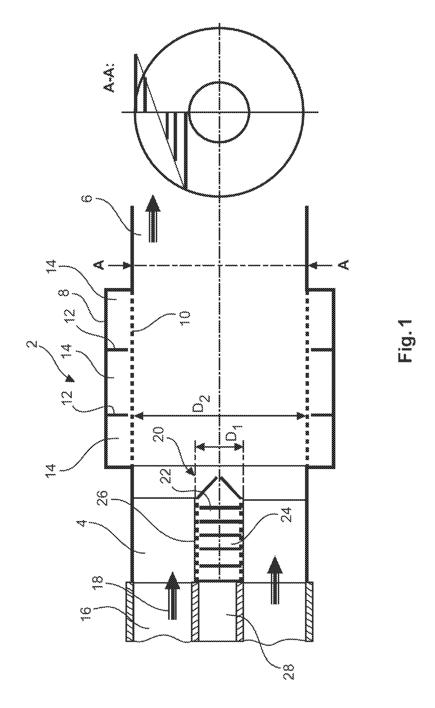
[0028]FIG. 1 shows a lateral section view of a silencer 2 according to an embodiment of the invention. The silencer 2 comprises an inlet 4, an outlet 6, a housing 8 situated between the inlet 4 and the outlet 6, and a flow channel 10, enclosed by the aforesaid, with a porous wall material. The housing 8 comprises several partitions 12, spaced apart from each other, that divide an intermediate space between the housing 8 and the flow channel 10 into several outer cells 14.

[0029]The inlet 4 is connected to an exhaust gas outlet 16 of an auxiliary power unit, APU. As indicated by the flow direction arrows 18, exhaust gas from the outlet 16 flows into the inlet 4, from there by way of the flow channel 10 to the outlet 6, and from there into the surroundings. The inlet and the flow channel 10 comprise, for example, the same diameter so that an even flow pattern in the transition from the inlet 4 to the flow channel 10 takes place.

[0030]During the inflow of the exhaust gas into the silenc...


PUM


Abstract

A silencer for an auxiliary power unit of an aircraft includes an inlet, an outlet, a housing, and a flow channel of a porous material, arranged in the housing. Between the housing and the flow channel an intermediate space is created, which space is divided by at least one outer partition into outer cells arranged around the flow channel. A central body includes a casing that is permeable to gas at least in some regions and that is arranged in the interior of the silencer. The central body includes inner partitions dividing the central body into inner cells. The resonance frequency of the inner cells corresponds to the natural frequency of the first radial mode in a channel formed between the central body and the inner surface of the inlet. In this manner particularly good sound attenuation is achieved with a compact installation space of a silencer.

Description

CROSS-REFERENCE TO RELATED APPLICATIONS[0001]The present application claims the benefit of the filing date of U.S. Provisional Patent Application No. 61 / 541,409, filed Sep. 30, 2011 and of German Patent Application No. 10 2011 114 705.9, filed Sep. 30, 2011, the disclosures of which are hereby incorporated herein by reference.TECHNICAL FIELD[0002]The invention relates to a silencer for an auxiliary power unit of an aircraft with a housing and a flow channel arranged in the housing, wherein the space between the flow channel and the housing is divided into several cells. The invention further relates to the use of a silencer for an auxiliary power unit in an aircraft and to an aircraft comprising at least one auxiliary power unit and at least one silencer arranged on said auxiliary power unit.BACKGROUND OF THE INVENTION[0003]Commercial aircraft frequently comprise an auxiliary power unit (also named “APU” for “Auxiliary Power Unit”) that is often situated in a tail cone of the aircra...

Claims


Application Information

Patent Timeline
Patent Type & Authority Patents(United States)
IPC IPC(8): F02K1/04F02K1/82
CPCB64D33/06B64D41/00F02K1/827F05D2220/50G10K11/172Y02T50/60
Inventor STAROBINSKI, RUDOLFSIERCKE, MATTHIAS
Owner AIRBUS OPERATIONS GMBH
Why Eureka
Try Eureka