
Dual microphone noise reduction for headset application

a dual-microphone and headset technology, applied in the field of headsets, can solve the problems of increasing noise, difficult to reduce non-stationary noise without significantly degrading voice quality, etc., and achieve the effects of reducing ambient noise, reducing noise, and reducing noise vocal signal

Active Publication Date: 2010-08-10
QUALCOMM TECH INT
View PDF5 Cites 72 Cited by
  • Summary
  • Abstract
  • Description
  • Claims
  • Application Information

AI Technical Summary

Benefits of technology

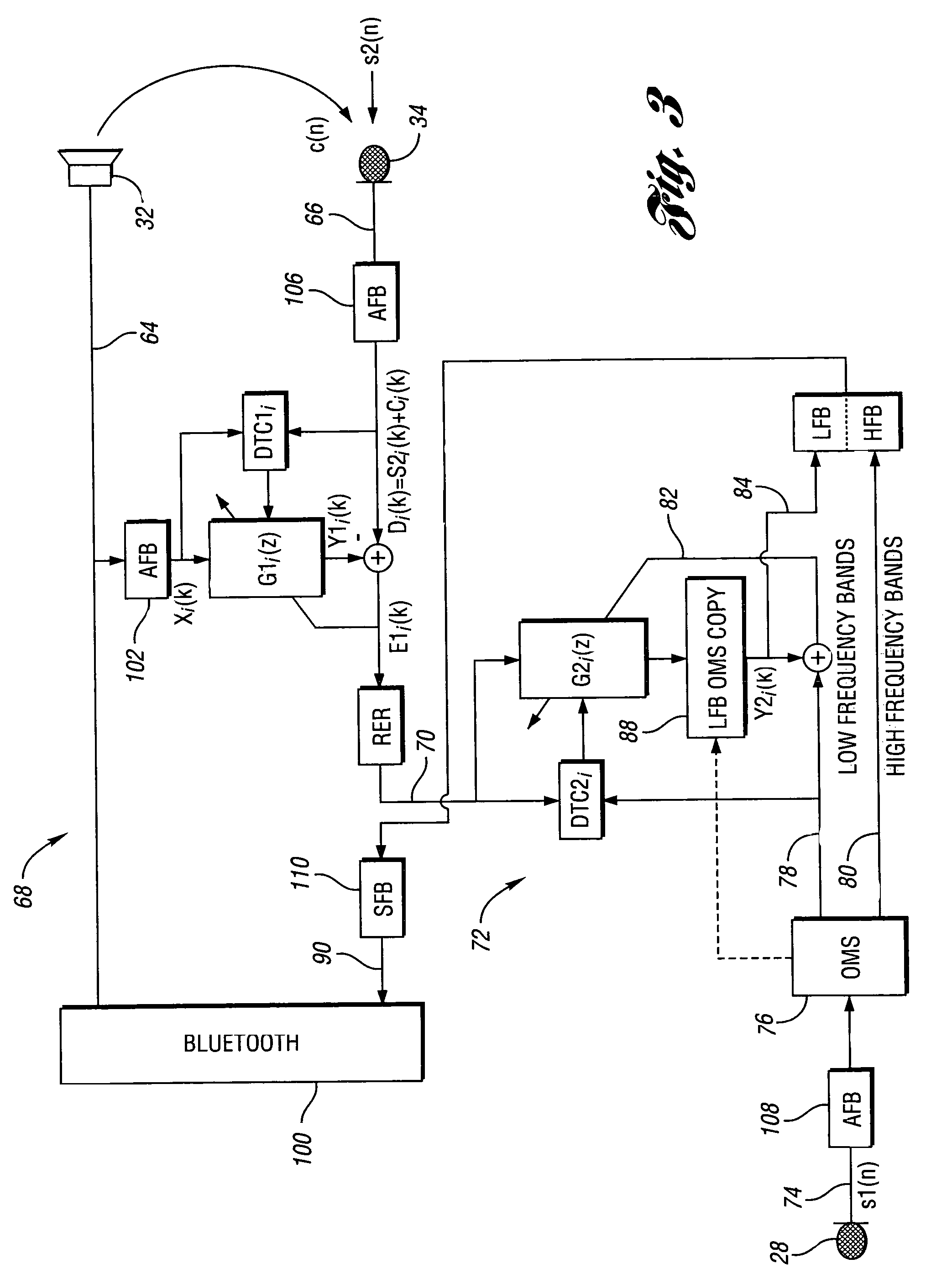
[0008]A system is provided including an ear portion forming a chamber reducing ambient noise from outside the chamber. A first microphone, located outside the chamber, is positioned to pick up vocal sound from a wearer of the system and to generate a first signal. A speaker provides sound to the chamber. A second microphone is disposed within the chamber and generates a second signal. An echo reducer reduces the effects of the speaker signal in the second signal. A dynamic equalizer adjusts the frequency spectrum of the second signal based on the first signal to produce a filtered signal.
[0009]In an embodiment of the present invention, a first noise reducer reduces noise in the first signal.
[0010]In another embodiment of the present invention, an output signal is produced by combining low frequency output based on the filtered signal with high frequency output based on the first signal. An echo reducer may reduce the effects of a speaker signal driving the speaker in the high frequency output.
[0015]A system for generating a reduced noise vocal signal based on speech spoken by a user is also provided. An ear portion forms a chamber with at least a portion of the user's ear. The chamber reduces ambient noise from outside the chamber. The chamber includes a speaker providing sound to the user's ear. A first microphone outside the chamber is positioned to pick up the user's speech and to generate a first signal based on the speech. The system includes a second microphone disposed within the chamber generating a second signal based on the speech spoken by the user. Audio processing circuitry generates the reduced noise vocal signal by processing the second signal based on the first signal.

Problems solved by technology

The effects of noise may increase as the headset size shrinks, moving the microphone farther away from the wearer's mouth.
Reducing non-stationary noise without significantly degrading voice quality is more challenging.

Method used


Image

  • Dual microphone noise reduction for headset application
  • Dual microphone noise reduction for headset application
  • Dual microphone noise reduction for headset application

Examples


Embodiment Construction

)

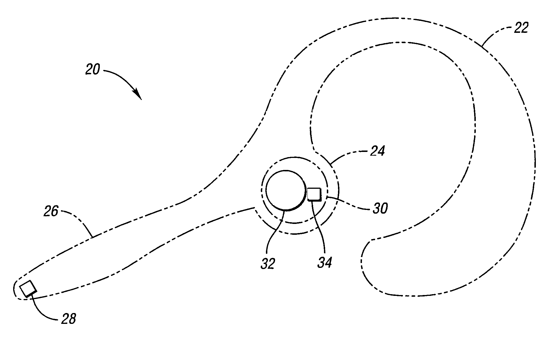
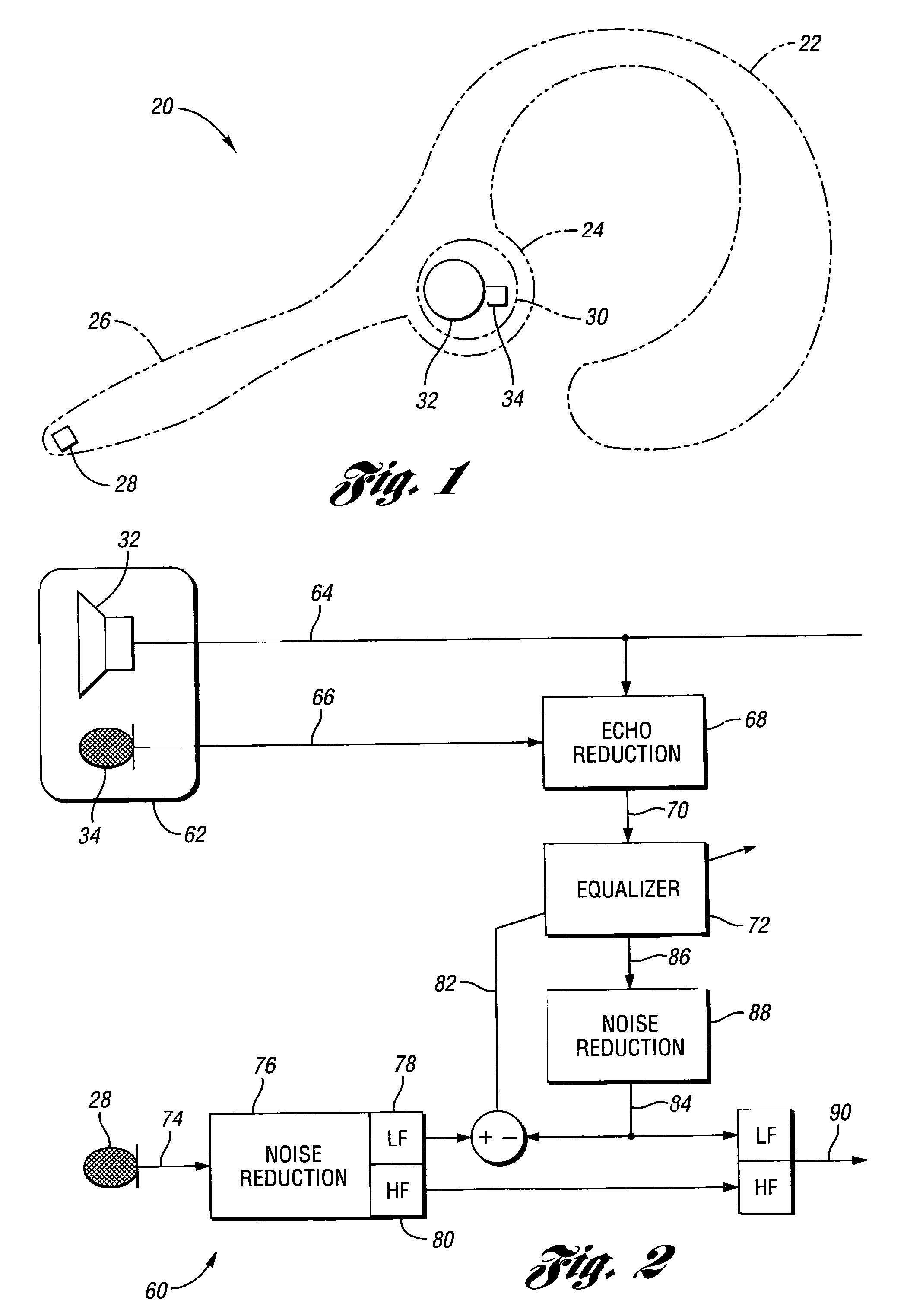
[0026]Referring to FIG. 1, a schematic diagram of headset that incorporates a second microphone according to an embodiment of the present invention. A headset, shown generally by 20, includes curved portion 22 which fits around the wearer's ear such that earpiece portion 24 fits within the ear. Boom portion 26 extends from earpiece 24 in the direction of the wearer's mouth. Details of curved portion 22, earpiece 24, and boom 26 are well known in the art and have been omitted from FIG. 1. Boom 26 places first microphone relative to the wearer's mouth. Earpiece 24 is formed so that insertion portion 30 fits at least partially within the ear canal of the wearer so as to form a chamber including speaker 32 and second microphone 34.

[0027]A wide variety of configurations may be used in the present invention. For example, first microphone 28 need not be rigidly or fixedly located relative to second microphone 34 such as, for example, if first microphone is located on a wire interconnectin...


PUM


Abstract

Improved vocal signals are obtained in headsets and similar devices by including a microphone inside a chamber formed at least in part by the wearer's ear. This second microphone provides a reduced noise input signal. The reduced noise signal is corrected by input from another microphone, located outside the chamber. This correction can include echo cancellation, spectral shaping, frequency extension, and the like.

Description

BACKGROUND OF THE INVENTION[0001]1. Field of the Invention[0002]This invention relates to headsets used in voice communication systems.[0003]2. Background Art[0004]Headsets allow the wearer to send and receive vocal communications. Headsets typically include a loudspeaker or other sound generator inside or near the ear canal of the wearer and a microphone near the mouth of the wearer. The boom in wireless communications has seen an increase in the use of headsets in a wide variety of environments. This boom has been further fueled by the development of short-range wireless technology, such as Bluetooth, which allows the headphone itself to be wirelessly connected to its corresponding telecommunications device.[0005]Increasingly, portable communication systems are being used in noisy environments such as, for example, automobiles, airports, streets, malls, restaurants, and the like. The effects of noise may increase as the headset size shrinks, moving the microphone farther away from...

Claims


Application Information

Patent Timeline
Patent Type & Authority Patents(United States)
IPC IPC(8): A61F11/06
CPCG10L21/02H04R3/02H04R3/04G10L2021/02165H04R1/1083H04R2410/05
Inventor ALVES, ROGERIO G.YEN, KUAN-CHIEH
Owner QUALCOMM TECH INT
Learn More