Digital processor sensor loop detector and method

a digital processor and sensor technology, applied in the field of conveying belts, can solve the problems of reducing the sensitivity of environmental variables, affecting the accuracy of environmental variables, so as to reduce the sensitivity to changes in environmental variables, reduce the sensitivity to environmental noise, and reduce the sensitivity to environmental variables. the effect of slits, cuts or tears

Active Publication Date: 2010-06-22
CONTITECH USA INC
View PDF33 Cites 21 Cited by
  • Summary
  • Abstract
  • Description
  • Claims
  • Application Information

AI Technical Summary

Benefits of technology

[0008]The present invention provides a sensor loop detector that utilizes digital processing to create sensor loop excitation signals and to analyze corresponding feedback signals from the sensor loops. Further, the sensor loop detector of the present invention is capable of automatically selecting a frequency for the sensor loop excitation signal having a minimum noise amplitude, thereby making the system less sensitive to environmental noise. In addition, the digital processing of the sensor loop detector has a greater read range with respect to the sensor loops than prior analogue detection circuits, thereby further reducing sensitivity to changes in environmental variables. The sensor loop detector of the present invention applies fixed duration excitation signal pulse strings on an intermittent basis to further reduce adverse effects of capacitive cross-coupling and environmental noise. Also, the sensor loop detector does not use an automatic gain control circuit that requires a large capacitance, thereby eliminating the costly requirements of providing associated electrical shielding and filtering.
[0012]In one aspect common to all embodiments of the invention, the digital processor provides excitation signals having a fixed duration, wherein the fixed duration terminates transmission of the excitation signal prior to determining the magnitude and phase values, thereby reducing an inherent capacitive cross-coupling that generates noise. In a further aspect of the invention, the excitation signal is a fixed duration pulse string.

Problems solved by technology

The belts so employed may be relatively long, on the order of miles, and represent a high cost component of an industrial material handling operation.
In many applications, the belts are susceptible to damage from the material transported thereby, and a rip (slit, cut or tear) may develop within the belt.
The cost of repairing a heavy duty conveyor belt and the cost of cleaning up material spilled from the damaged belt can be substantial.
If, however, such a rip or tear commences and the belt is not immediately stopped, the rip can propagate for a substantial distance along the belt.
First, in some operational environments, the electrical noise is so great that a poor signal-to-noise ratio significantly decreases the accuracy of the rip detector function.
Moreover, it has been observed that with a conveyor belt carrying antennas intended for inductive coupling, much of the electrical noise introduced to the receiver is derived from capacitive cross-coupling.
The magnitude of the electrical noise signal in a conveyor belt rip detector often approaches the magnitude of the transmitter signal; and, therefore, it is quite difficult to sense a received transmitter signal with accuracy, especially in particularly electrically noisy environments in which conveyor belt rip detectors often are found.
Second, wear, stretching, contraction, dirt, other environmental conditions, etc. may cause a variation in the efficiency of signal coupling, whether of the capacitive, inductive, optical, or any other type of coupling, between the sensor loops (or other signal coupling means carried by the belt) and the transmitter and the receiver at a rip detector station.
Such efficiency variation will vary the magnitude or other parameter of the input signal delivered from the receiver to the detector, which may detrimentally affect operation of the entire system.
Fourth, many known systems use inductive coupling to excite the conductive sensor loops in the belt; and known automatic gain control circuits utilize a relatively large capacitance.
Such a large capacitance requires electrical shielding and filtering and hence, is relatively costly.

Method used


Image

  • Digital processor sensor loop detector and method
  • Digital processor sensor loop detector and method
  • Digital processor sensor loop detector and method

Examples


Embodiment Construction

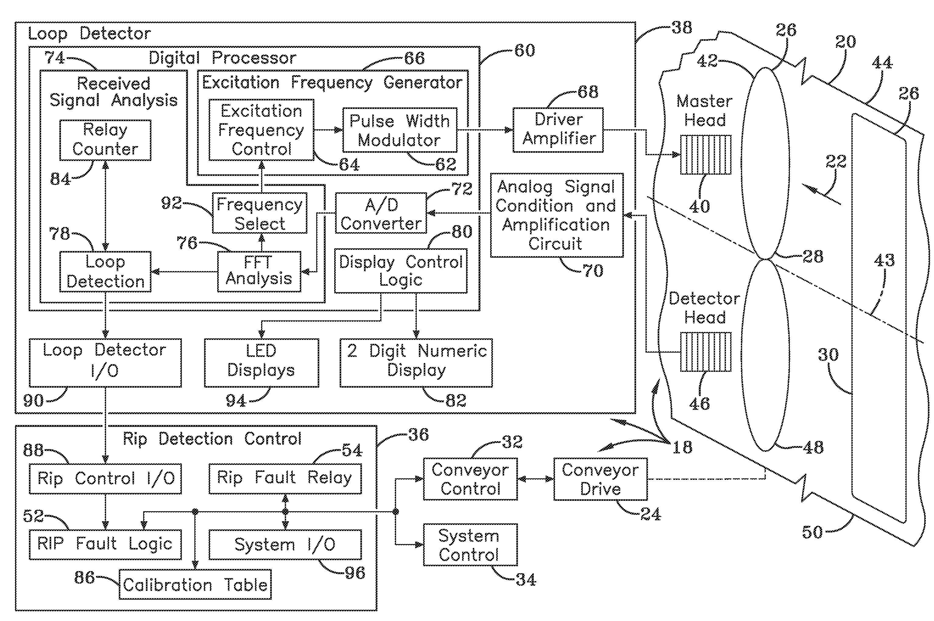
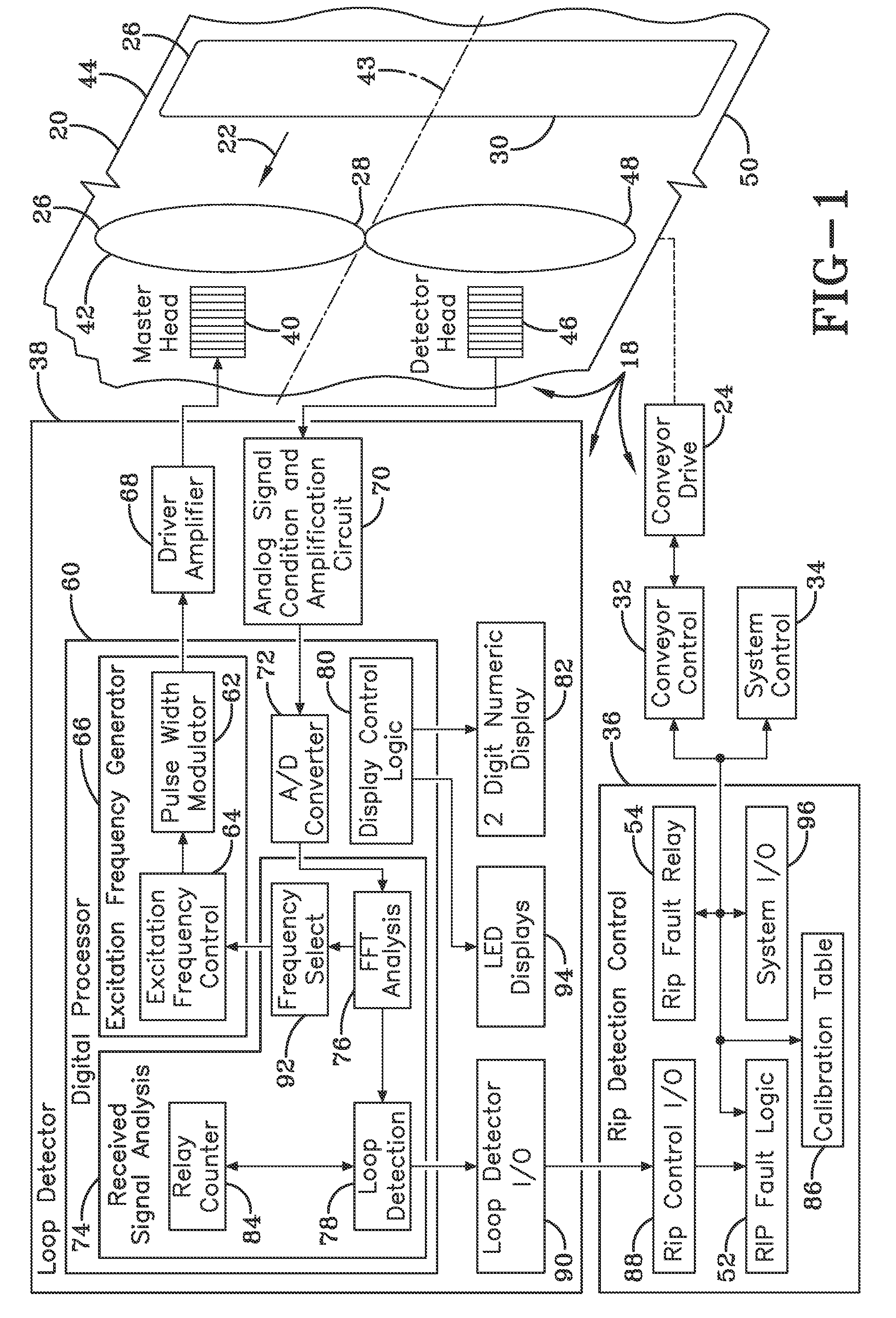
[0024]Referring to FIG. 1, an exemplary embodiment of a rip detection system 18 is applied to a conveyor belt 20 that is moved in a direction indicated by the arrow 22 by a conveyor drive 24 in a known manner. A series of sensor loops 26 are supported by the conveyor belt 20. The sensor loops 26 extend transversely across the conveyor belt 20 and are spaced apart over a length of the conveyor belt. The sensor loops 26 can be made of one or more conductors and have different configurations, for example, an inverted or figure eight configuration 28 or a loop configuration 30. The exact spacing between the sensor loops 26 depends on the type of conveyor belt 20 and its intended application. The conveyor drive 24 contains the necessary pulleys, shafts, motors and other known mechanical and electromechanical components. The conveyor drive 24 is electrically connected to a conveyor control 32 which, in turn, is often in electrical communications with an overall system control 34. In this ...


PUM


Abstract

A digital processor for use in a conveyor belt rip detector, which provides excitation signals at a selected frequency to inverted and noninverted sensor loops on a conveyor belt and then, detects corresponding received signals from the sensor loops. The digital processor then performs FFTs on the corresponding received signals to provide respective received signal frequency spectrums. Next magnitude and phase values of the selected frequency in the respective received signal frequency spectrums are used to determine a qualitative state of the sensor loops. The selected frequency has a lowest detected ambient noise level, and the magnitude value is a normalized magnitude value.

Description

FIELD OF THE INVENTION[0001]This invention relates generally to conveyor belts and, more particularly, to an improved system for detecting damage or rips to conveyor belts.BACKGROUND OF THE INVENTION[0002]In a multitude of commercial applications, it is common to employ a heavy duty conveyor belt for the purpose of transporting product and material. The belts so employed may be relatively long, on the order of miles, and represent a high cost component of an industrial material handling operation. In many applications, the belts are susceptible to damage from the material transported thereby, and a rip (slit, cut or tear) may develop within the belt. A torn or ripped belt can be repaired once detected. The cost of repairing a heavy duty conveyor belt and the cost of cleaning up material spilled from the damaged belt can be substantial. If, however, such a rip or tear commences and the belt is not immediately stopped, the rip can propagate for a substantial distance along the belt. I...

Claims


Application Information

Patent Timeline
Patent Type & Authority Patents(United States)
IPC IPC(8): G08B21/00G01M13/023
CPCG01M13/023B65G43/02B65G43/06G01N23/18G01N27/61G06F17/14
Inventor WALLACE, JACK BRUCEGARTLAND, JOHN JAMESBLAUSEY, RICHARD HERMANKEREKES, JR., EDWARD LOUIS
Owner CONTITECH USA INC
Why Eureka
Try Eureka