Wireless identification device, RFID device with push-on/push off switch, and method of manufacturing wireless identification device

a wireless identification and push-on/push-off switch technology, applied in the field of radio frequency communication devices, can solve the problems of battery drain, battery may be drained, identification systems are only capable of operating over a relatively short range, etc., and achieve the effect of greater rang

Inactive Publication Date: 2006-03-14
ROUND ROCK RES LLC
View PDF40 Cites 101 Cited by
  • Summary
  • Abstract
  • Description
  • Claims
  • Application Information

AI Technical Summary

Benefits of technology

[0015]One embodiment of the invention provides a radio frequency identification device comprising an integrated circuit including a receiver, a transmitter, and a microprocessor. In one embodiment, the integrated circuit is a monolithic single die single metal layer integrated circuit including the receiver, the transmitter, and the microprocessor. The device of this embodiment includes an active transponder, instead of a transponder which relies on magnetic coupling for power, and therefore has a much greater range.

Problems solved by technology

As large numbers of objects are moved in inventory, product manufacturing, and merchandising operations, there is a continuous challenge to accurately monitor the location and flow of objects.
However, such identification systems are only capable of operation over a relatively short range, limited by the size of a magnetic field used to supply power to the devices and to communicate with the devices.
For active devices, battery drain is an important issue.
The battery may be drained by spurious emissions of the radiation necessary to activate a radio frequency identification device.
A power conservation problem is posed by such implementations where batteries are used to supply power to the circuitry of the radio frequency identification device.
If the circuitry operates continuously at full power, battery life will be short, and device will have to be frequently replaced.
If the battery is permanently sealed in a housing, replacement of the battery will be difficult or impossible.
One potential problem with existing radio frequency identification devices, particularly those with large communication ranges, is that the holder of the device may not have control over when the device is being interrogated.

Method used


Image

  • Wireless identification device, RFID device with push-on/push off switch, and method of manufacturing wireless identification device
  • Wireless identification device, RFID device with push-on/push off switch, and method of manufacturing wireless identification device
  • Wireless identification device, RFID device with push-on/push off switch, and method of manufacturing wireless identification device

Examples


Embodiment Construction

[0027]This disclosure of the invention is submitted in furtherance of the constitutional purposes of the U.S. Patent Laws “to promote the progress of science and useful arts” (Article 1, Section 8).

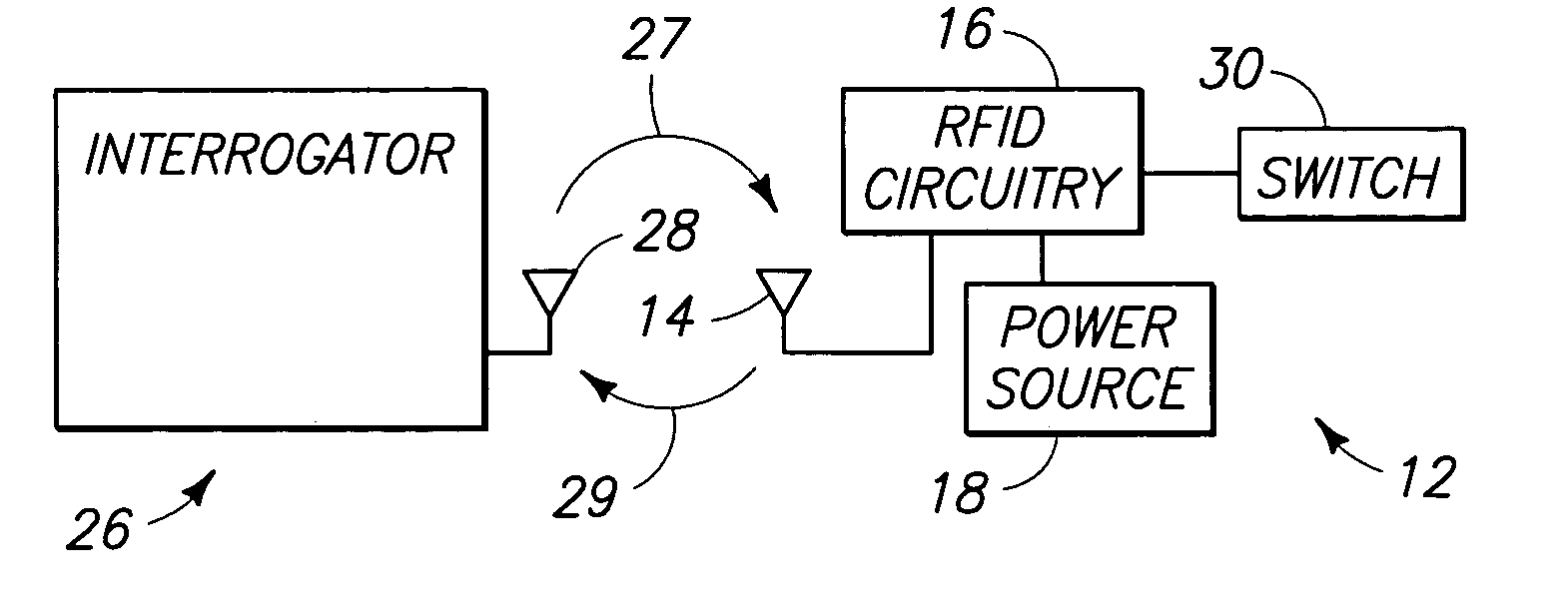
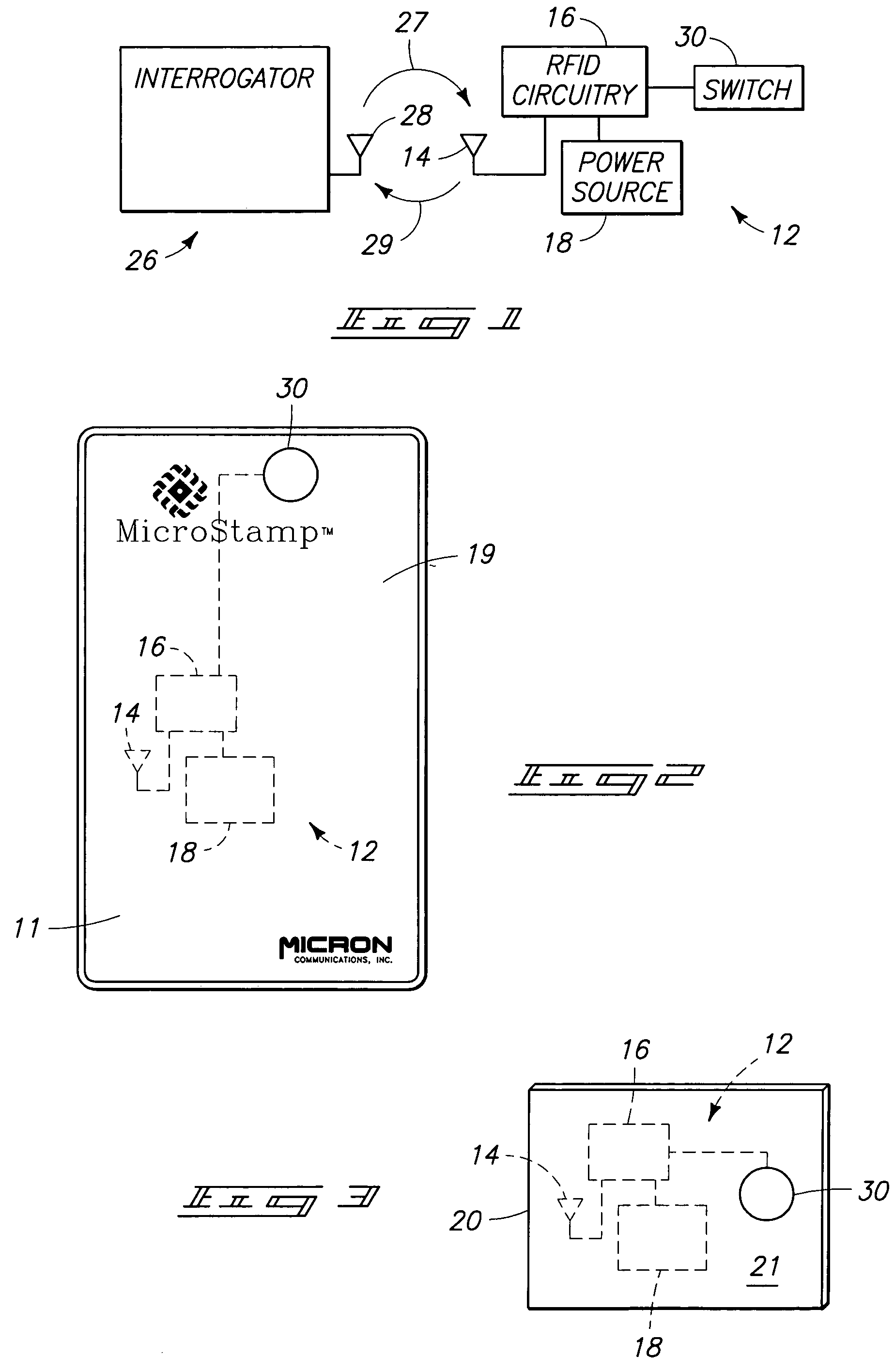
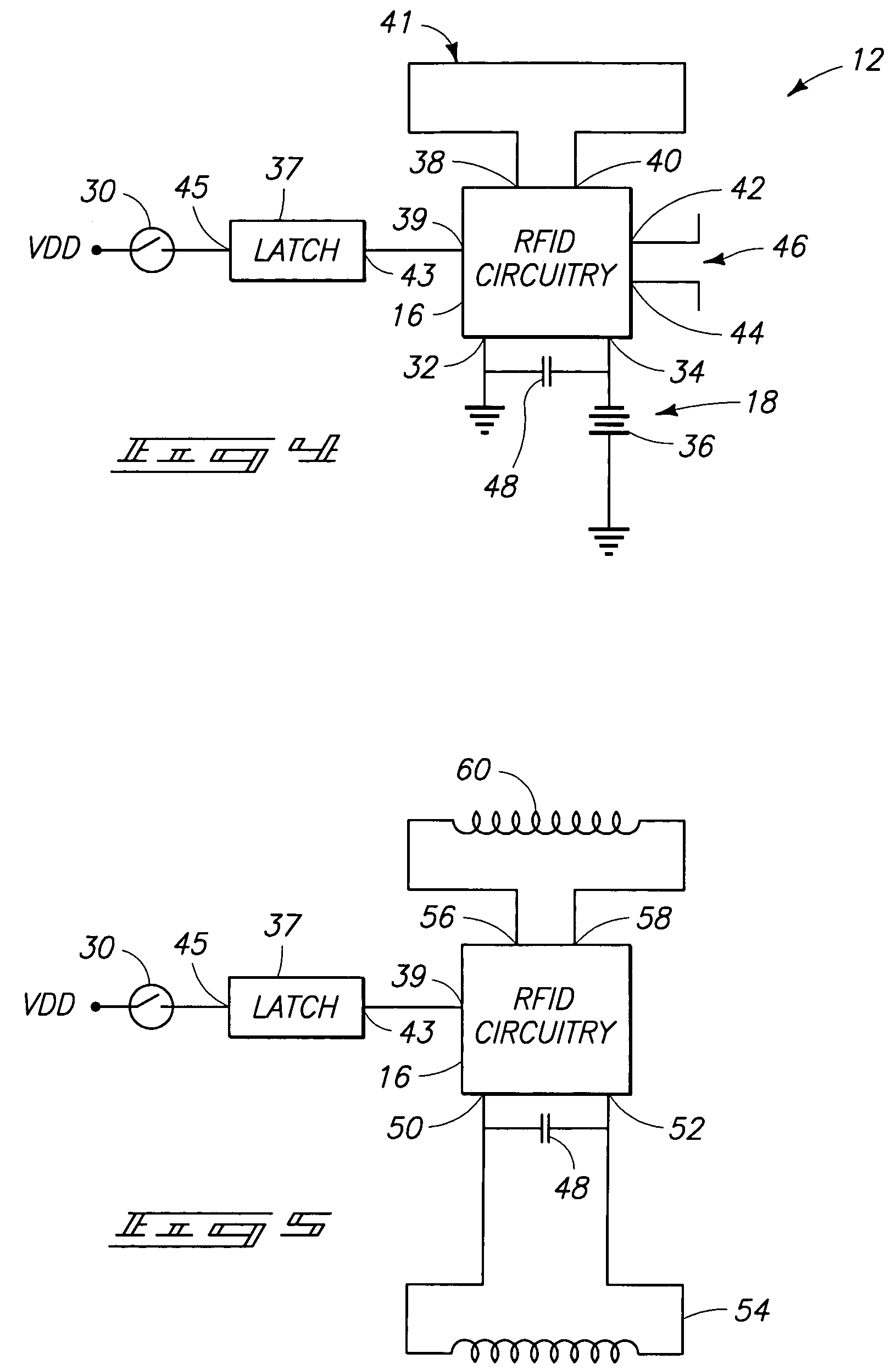
[0028]FIG. 1 illustrates a radio frequency data communication device 12 in accordance with one embodiment of the invention. In the illustrated embodiment, the radio frequency data communication device 12 includes RFID circuitry 16. In the illustrated embodiment, the RFID circuitry is defined by an integrated circuit as described in the above-incorporated patent application Ser. No. 08 / 705,043, filed Aug. 29, 1996. Other embodiments are possible. A power source 18 is connected to the integrated circuit 16 to supply power to the integrated circuit 16. In one embodiment, the power source 18 comprises a battery. In an alternative embodiment, the power source 18 comprises a magnetic coil that receives power via magnetic coupling from an external reader as is known in the art; e.g., as disclose...


PUM

PropertyMeasurementUnit
radio frequencyaaaaaaaaaa
magnetic couplingaaaaaaaaaa
poweraaaaaaaaaa

Abstract

A wireless identification device including a housing; circuitry in the housing configured to provide a signal to identify the device in response to an interrogation signal; and a selectively actuated switch supported by the housing and controlling whether the circuitry identifies the device. A method of manufacturing a wireless identification device, the method comprising configuring circuitry to provide a signal to identify the device in response to an interrogation signal; coupling the circuitry to a push-on / push-off switch supported by the housing and controlling whether the circuitry provides the signal to identify the device; and encasing the circuitry in a housing such that the switch is actable from outside the housing by touching a portion of the housing.

Description

[0001]This is a continuation of application Ser. No. 10 / 117,737, filed Apr. 1, 2002, now U.S. Pat. No. 6,693,513.TECHNICAL FIELD[0002]This invention relates to radio frequency communication devices. More particularly, the invention relates to radio frequency identification devices for inventory control, object monitoring, determining the existence, location or movement of objects, or for remote automated payment.BACKGROUND OF THE INVENTION[0003]As large numbers of objects are moved in inventory, product manufacturing, and merchandising operations, there is a continuous challenge to accurately monitor the location and flow of objects. Additionally, there is a continuing goal to interrogate the location of objects in an inexpensive and streamlined manner. One way of tracking objects is with an electronic identification system.[0004]One presently available electronic identification system utilizes a magnetic coupling system. In some cases, an identification device may be provided with ...

Claims


Application Information

Patent Timeline
Patent Type & Authority Patents(United States)
IPC IPC(8): H04Q1/00G06K19/07G06K19/073G06K19/077
CPCG06K19/0716G06K19/0723G06K19/07345G06K19/07749H01Q9/16H01Q21/28H01Q7/00H01H2231/05Y10T29/49016Y10T29/49018Y10T29/49004Y10T29/49117
Inventor TUTTLE, MARK E.
Owner ROUND ROCK RES LLC
Why Eureka
Try Eureka