
Complex signal decomposition and modeling

Inactive Publication Date: 2005-10-18
SMARTSIGNAL CORP
View PDF94 Cites 105 Cited by
  • Summary
  • Abstract
  • Description
  • Claims
  • Application Information

AI Technical Summary

Benefits of technology

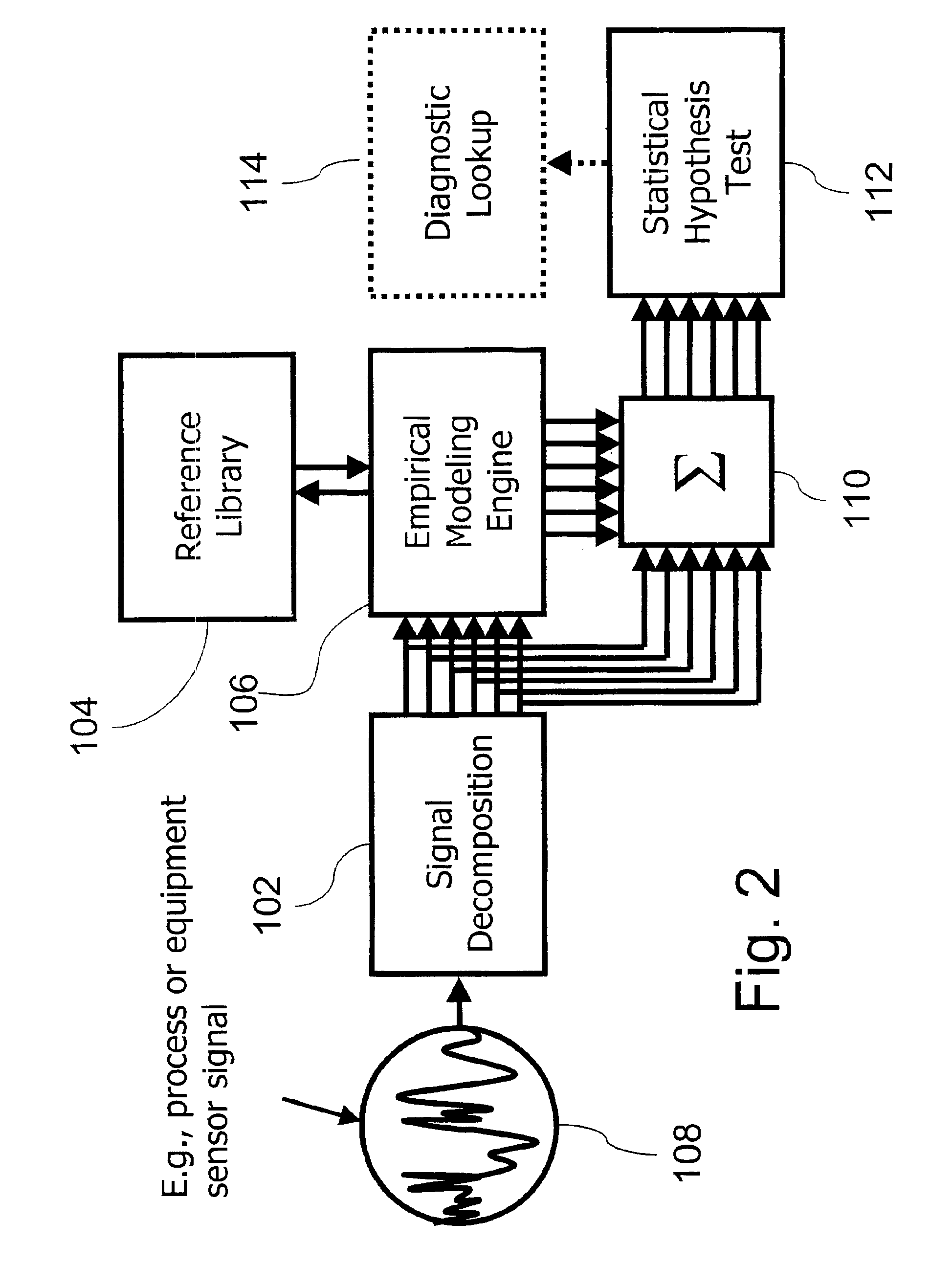
[0012]A complex signal or parameter, such as a time varying electrical signal (e.g., a electrocardiogram), is decomposed into multiple related signals by band notch filtering, wavelet analysis or other means. The multiple signals essentially form multivariate inputs to an empirical modeling engine, which generates signal estimates in response to the inputs. The modeling engine utilizes a stored reference set of prior known multivariate snapshots to generate the estimates. The estimates and the actual signals are compared in a sensitive statistical test to detect deviations between them, indicative of an unrecognized operational state. Alternatively, the empirical modeling engine compares the multivariate input snapshot to the snapshots in the reference set to determine which reference set snapshots are most similar to the input. A classification associated with the stored reference snapshots having the highest similarity is selected as the classification of the inputs, and the operational state represented by the complex signal is thus determined from a finite set of such known states represented in the reference set. Accordingly, not only can operational states of a system providing the complex signal be categorized, but also original datagrams can be reconstructed from degraded encoding carrier waves for digital data transmission, thereby affording greater range and accuracy.

Problems solved by technology

Such methods focus on using the instantaneous value of sensors and other parameters to describe the current state of a system, but do not take advantage of time-domain information locked up in the sensor signals.
If a threshold is pierced, this is indicative of an unsatisfactory operating condition or a developing problem.
However, during transmission these types of signals can suffer from attenuation and interference due to noise or transmission media deterioration, for example.
In some cases, noise and signal degradation is sufficient to all but obliterate the original transmitted signal, making it impossible to extract the data encoded therein using prior art techniques.
Discrepancies between the estimates and the actual values from the sensors indicate a developing process or machine failure, or sensor failure.
However, the described embodiments therein do not utilize the time domain information in the sensor signals, and instead usually treat the data in distinct and disconnected time-contemporaneous snapshots.

Method used


Image

  • Complex signal decomposition and modeling
  • Complex signal decomposition and modeling
  • Complex signal decomposition and modeling

Examples


Embodiment Construction

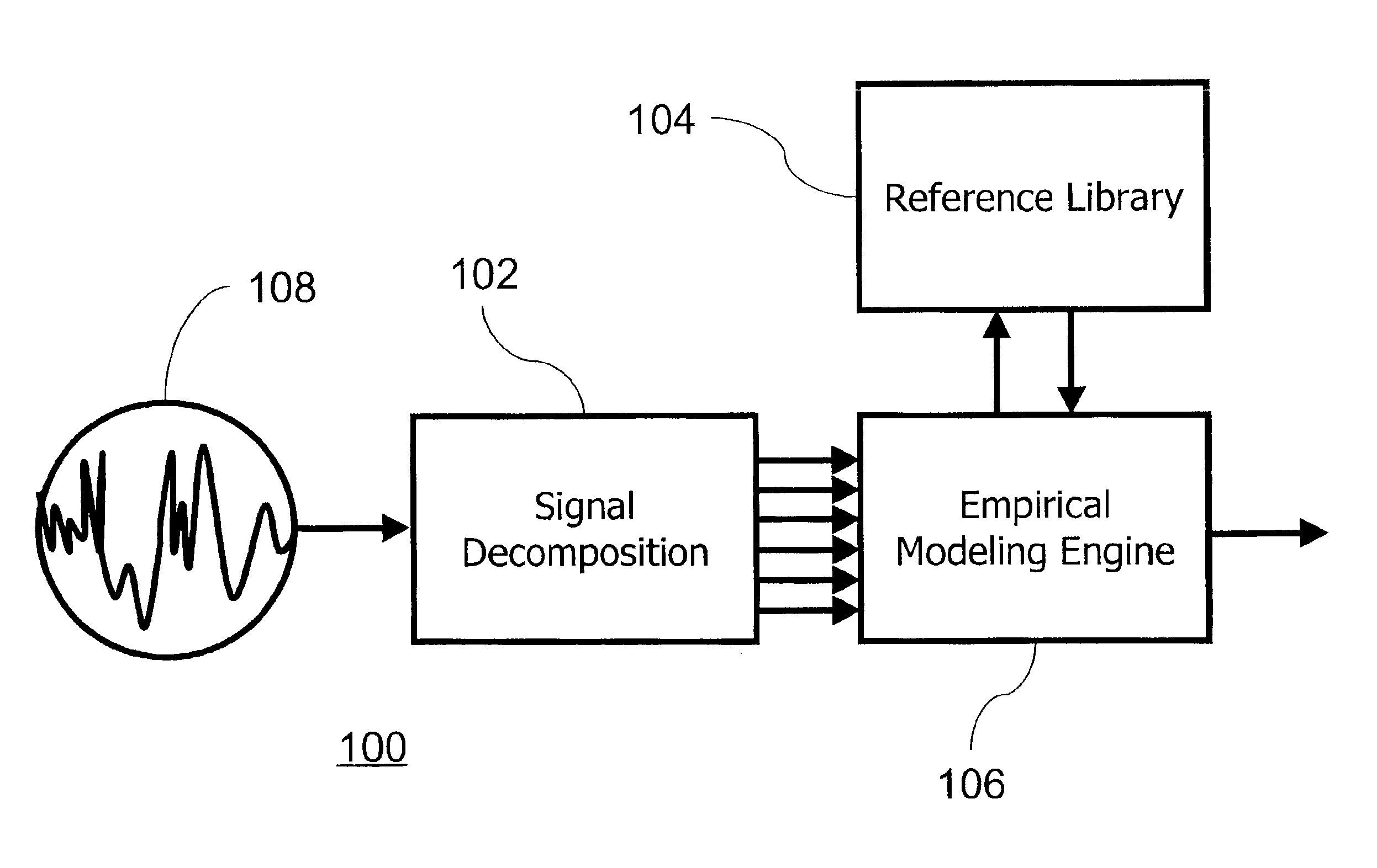
[0023]Turning now to the drawings and, more particularly, FIG. 1 generally shows the preferred embodiment signal decomposition and modeling system 100 of the present invention, which generally includes a signal receiver 108, a signal decomposition module 102, a reference library 104 and an empirical modeling engine 106. Signal receiver 108 serves to provide the complex signal to the signal decomposition module 102, which converts the signal to a plurality of correlated component signals. Empirical modeling engine 106 is disposed to receive the plurality of inputs, and with reference to a set of data embodying classification information or known operational information stored in reference library 104, output an indication about the complex signal and the system it is drawn from.

[0024]System 100 has application to any complex signal, whether naturally occurring, derived from a system, system operation or a process being carried out in a system or otherwise generated, naturally or arti...


PUM


Abstract

A system, method and program product for monitoring a complex signal for ultrasensitive detection of state changes, or for signature recognition and classification is provided. A complex signal is decomposed periodically for empirical modeling. Wavelet analysis, frequency band filtering or other methods may be used to decompose the complex signal into components. A library of signature data may be referenced for selection of a recognized signature in the decomposed complex signal. The recognized signature may indicate data being carried in the complex signal. Estimated signal data may be generated for determination of an operational state of a monitored process or machine using a statistical hypothesis test with reference to the decomposed input signal.

Description

CROSS REFERENCE TO RELATED APPLICATIONS[0001]This application claims the benefit of priority under 35 U.S.C.§ 119(e) to U.S. Provisional application Ser. No. 60 / 187,949 filed Mar. 9, 2000.BACKGROUND OF THE INVENTION[0002]1. Field of the Invention[0003]The present invention relates to process modeling and monitoring, especially using complex or periodic signals. Moreover, the invention relates to complex signal decomposition, modeling and classification for use in monitoring the operational state of any machine, process or signal. More particularly, a complex signal can be classified using the present invention for health monitoring or for information rectification.[0004]2. Description of the Related Art[0005]Well known conventional modeling and analysis methods use several sensors measuring operational system parameters to monitor equipment or processes—generically “systems”. The related signals from sensors can be observed directly to understand how the system is functioning. Alter...

Claims


Application Information

Patent Timeline
IPC IPC(8): G01R13/00G05B13/02G05B23/02G06F15/00G06F19/00H04B1/00H04B17/00G06K9/00H04B
CPCG06K9/00536G06F18/00G06F2218/12
Inventor WEGERICH, STEPHAN W.
Owner SMARTSIGNAL CORP
Learn More