Obstacle and terrain avoidance sensor

a technology of obstacle and terrain avoidance and sensor, which is applied in the direction of measuring devices, using reradiation, instruments, etc., can solve the problems of large percentage of severe and fatal helicopter and other aircraft accidents, reliance on gps or a comparable navigation system, and may not always be available, so as to improve accuracy, improve accuracy, and improve accuracy

Inactive Publication Date: 2004-09-16
RODRADAR LTD
View PDF41 Cites 103 Cited by
  • Summary
  • Abstract
  • Description
  • Claims
  • Application Information

AI Technical Summary

Benefits of technology

0266] d) Employ, in parallel to the basic FFT processes mentioned above, a higher resolution FFT process. As an example, an FFT process with a duration of one second will provide 1 Hz resolution, and will have a better chance to separate the object's backscatter from the ground reflections, meaning that they do not fall within the object's Doppler filter. It can be shown that a ground return which was still not separated from the object's backscatter using 1 Hz filters will not cause a significant elevation error. The higher resolution FFT will provide better elevation accuracy at a longer delay, and after the object has already been detected and its elevation calculated through the regular resolution FFT. It is not advisable, however, to delay the display of the object until the higher resolution result is available. Ins

Problems solved by technology

Controlled flight into terrain (CFIT) and collision with obstacles account for a large percentage of severe and fatal helicopter and other aircraft accidents, especially at night, adverse weather and otherwise bad visibility.
Another shortcoming of the category is the reliance on GPS or a comparable navigation system, which may not always be available, or in the case of a military mission, might be jammed.
Both MMW and laser sensors generally use mechanical scanning, which contributes to high cost, high weight and low reliability.
Short wavelength (MMW or laser) requires expensive components.
Furthermore, short wavelength radiation does not penetrate rain, fog, smoke and dust well and laser has a diff

Method used


Image

  • Obstacle and terrain avoidance sensor
  • Obstacle and terrain avoidance sensor
  • Obstacle and terrain avoidance sensor

Examples


Embodiment Construction

[0149] Doppler Processing

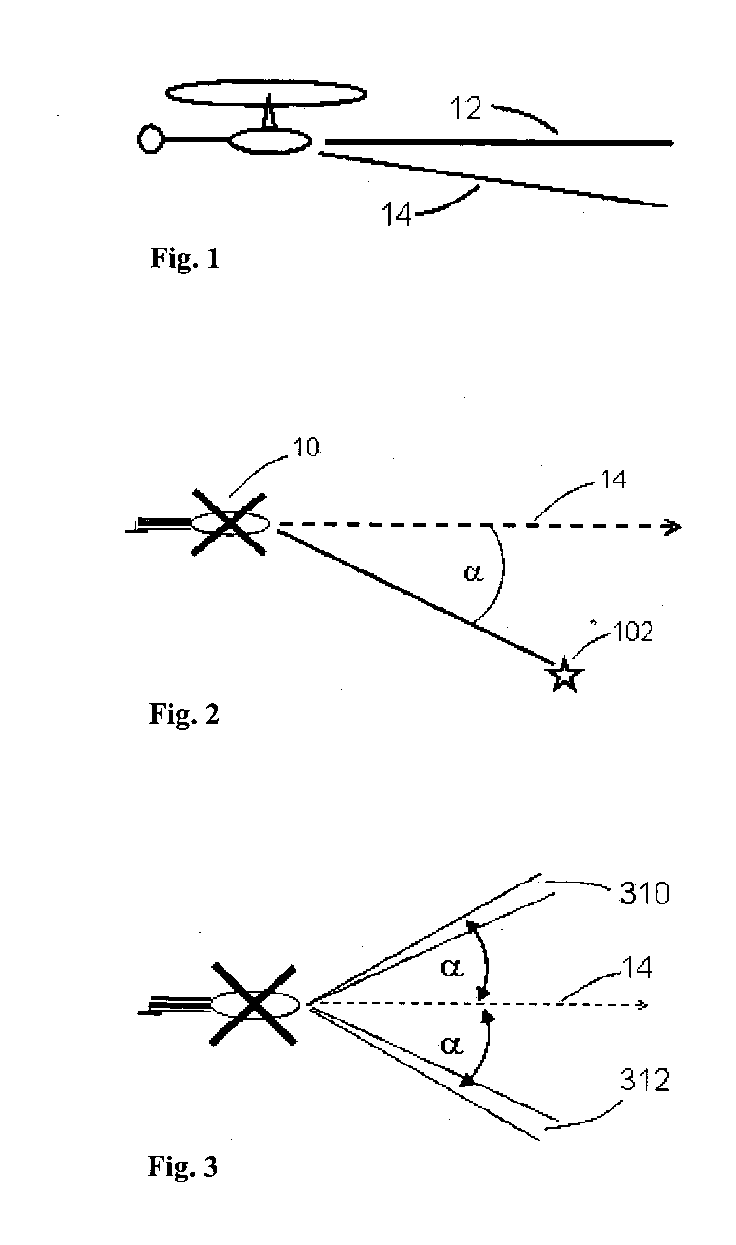
[0150] FIG. 1 shows an airborne vehicle 10, such as a helicopter moving in a direction shown by Line of Flight (LOF) 12, at a velocity V.sub.g. The Doppler shift, f.sub.d of the reflection of a terrain element 102 in an airborne radar is proportional to the cosine of .alpha., the angle between the LOF and the terrain element and is equal to:

f.sub.d=(2v.sub.g cos .alpha.) / .lambda. (Eq. 1)

[0151] where .lambda. is the wavelength of the radar irradiation.

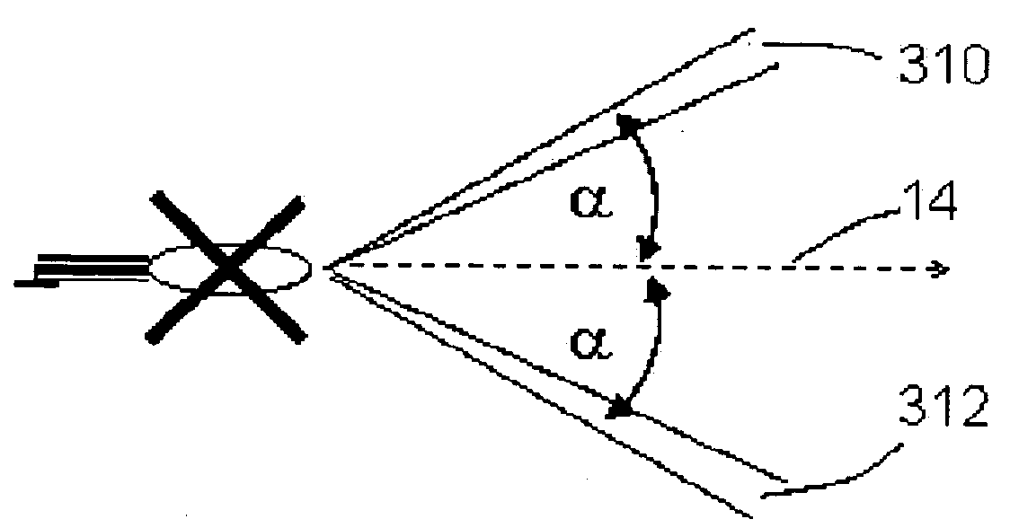
[0152] If vehicle 10 flies at a very low altitude over horizontal, flat terrain, then spectrum analysis of the signal received effectively divides the sector of terrain covered by the radar into many narrow sectors, where each portion of Doppler spectrum represents two terrain sectors, symmetrically located about the LOF. Two such sectors 310 and 312 are shown in FIG. 3.

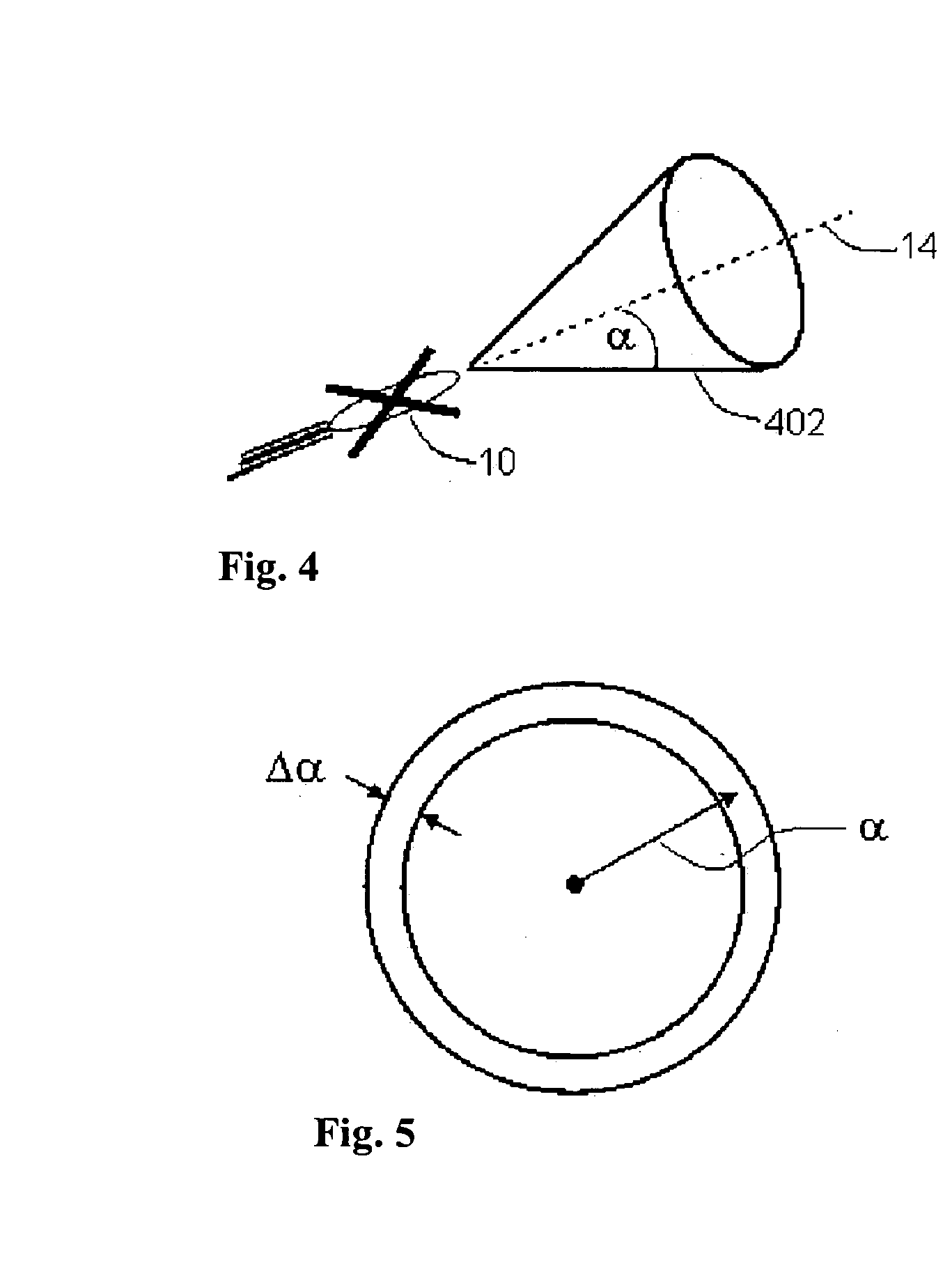
[0153] This principle, known as Doppler beam sharpening (DBS) is applicable not only to a horizontal plane, but to any plane containing the LOF,...


PUM


Abstract

A method of terrain mapping and/or obstacle detection for aircraft, comprising: (a) transmitting a non-scanning beam that illuminates the terrain and/or obstacles; (b) receiving a Doppler shifted signal that is Doppler frequency shifted by an amount dependent on an angle between a line of flight of the aircraft and scatterers that reflect the transmitted beam; (c) determining the angle from the Doppler frequency; (d) determining the range of at least some of said scatterers; and (e) determining the azimuth and elevation of the scatterers.

Description

[0001] The present invention is related to the field of terrain and obstacle avoidance for aircraft.[0002] Controlled flight into terrain (CFIT) and collision with obstacles account for a large percentage of severe and fatal helicopter and other aircraft accidents, especially at night, adverse weather and otherwise bad visibility. The need for a device that would provide adequate warning against obstacles and CFIT for military aircraft is well known. The need also exists for commercial aircraft which are required to fly low, take off from, and land at unprepared and unknown sites, frequently at night and in adverse weather. These include medical evacuation (MEDEVAC), search and rescue (S&R) and police helicopters.[0003] Many schemes have been devised in order to provide the required warnings. Most of these can be divided into two categories:[0004] The first category includes systems which rely on an accurate navigation system, such as the global positioning system (GPS), and a store...

Claims


Application Information

Patent Timeline
IPC IPC(8): G01S13/50G01S13/89G01S13/935
CPCG01S13/50G01S13/94G01S13/89G01S13/935
Inventor NIV, HAIM
Owner RODRADAR LTD
Why Eureka
Try Eureka