[0023] The present invention also provides methods for performing additional
ligation or reaction steps on isolated fractions of a sample material following extraction from the separation conduit by, for example, intermixing such components with additional reagents, such as marker compounds, e.g., molecular weight standards, labeling compounds, MALDI matrixes, and the like, for
mass spectroscopy, or
ligation agents, such as ligase enzymes (e.g., Topo-
isomerase), plasmids, and the like, for performing
cloning operations. By combining the separation step with an isolation function, one eliminates additional sample
fragment processing steps such as manual fragment extraction,
staining, UV illumination, physical
cutting,
plasmid incorporation, and the like, that are typically carried out separately from the
separation system, e.g., in multiwell plates or in individual test tubes.
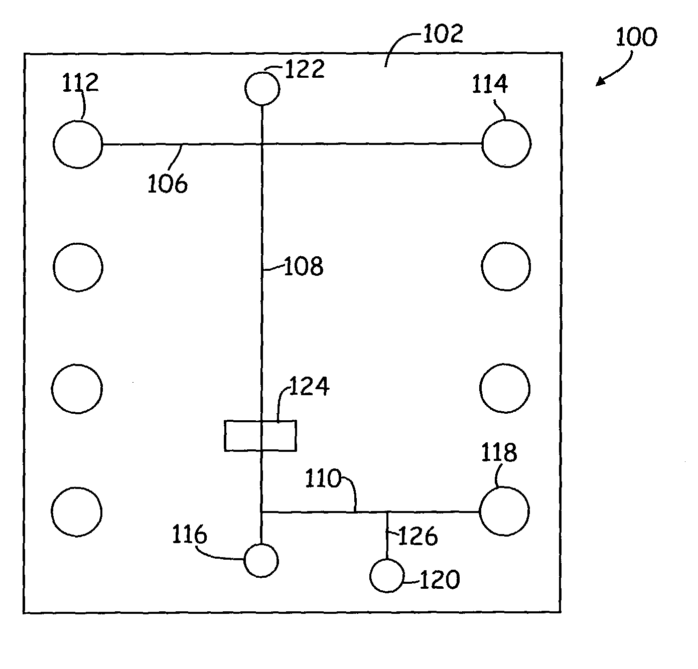
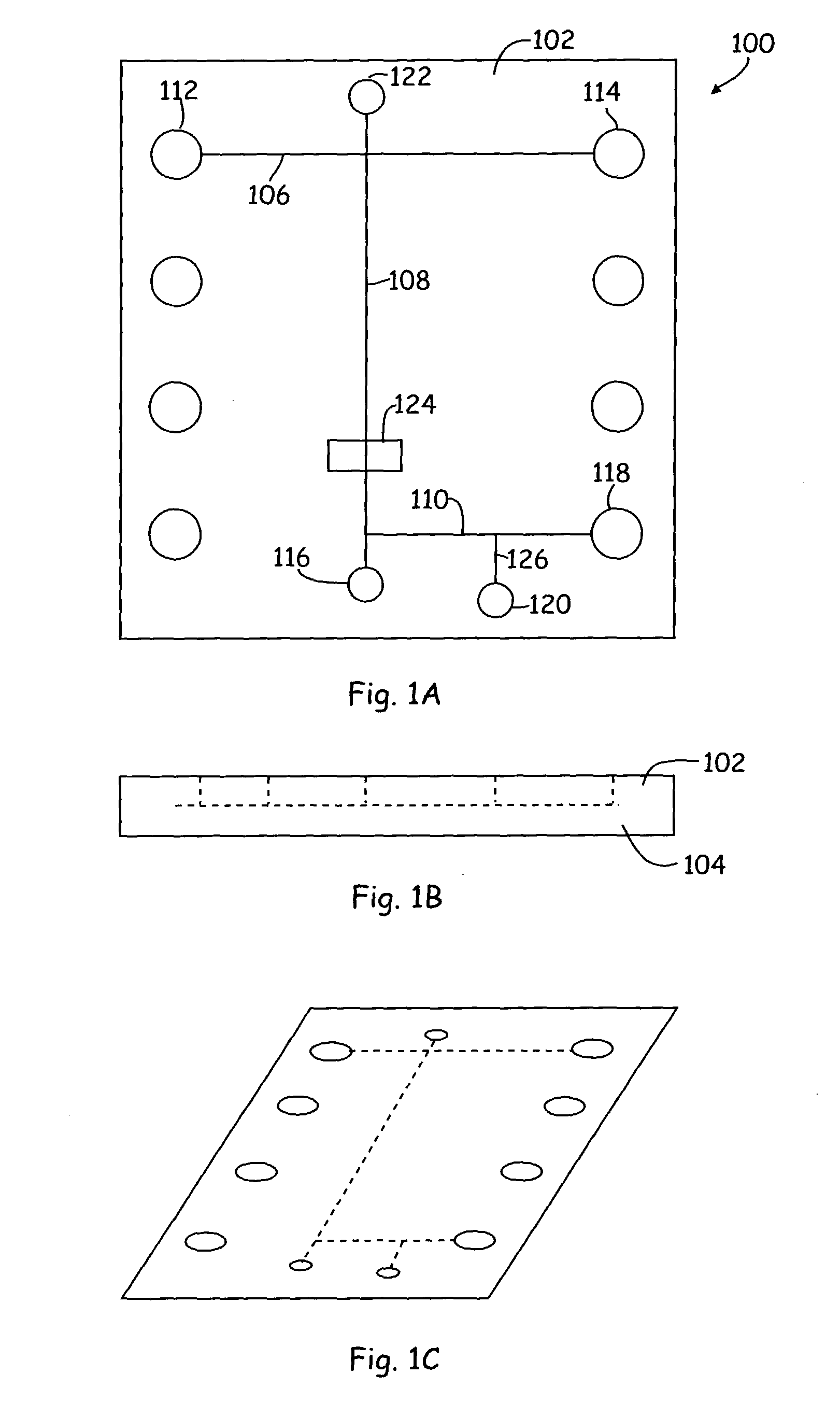
[0035] In accordance with the present invention, the sample loading conduit(s) 106, separation conduit 108, and collection conduit 110 are provided substantially within the integrated body structure. In particularly preferred aspects, these conduits are of microscale dimensions, meaning that they have at least one cross-sectional dimension that is less than 500 .mu.m, e.g., between about 0.1 and about 500 .mu.m, and preferably between about 1 .mu.m and about 200 .mu.m, and more preferably between about 1 .mu.m and about 100 .mu.m. Such
integrated devices typically provide numerous advantages over larger-scale systems as a result of their precise tolerances and the accuracy with which their operations can be controlled.
[0042] In certain preferred aspects, e.g., in
protein separations, a post separation
dilution step is employed to dilute out the amount of detergent, i.e., SDS, to below a critical micellar concentration, in order to optimize the detection of labeled proteins versus-the free detergent micelles. Such post column treatments are described in detail in U.S.
patent application Ser. No. 09 / 243,149, filed Feb. 2, 2000, and incorporated herein by reference in its entirety for all purposes. In such
protein separation methods, the
separation matrix includes a separation buffer, where the separation buffer typically includes a non-crosslinked
polymer solution, a
buffering agent, a detergent and a lipophilic dye. Non-crosslinked
polymer solutions that are suitable for use in
protein separations according to the present invention are described, for example, in commonly owned U.S. application Ser. No. 08 / 992,239, filed Dec. 11, 1997, which is incorporated by reference herein in its entirety. Preferably, the detergent and
buffering agent are present within the separation buffer at concentrations that are at or below the
critical micelle concentration ("CMC"). In this way, adverse effects such as
dye binding to detergent micelles can be minimized.
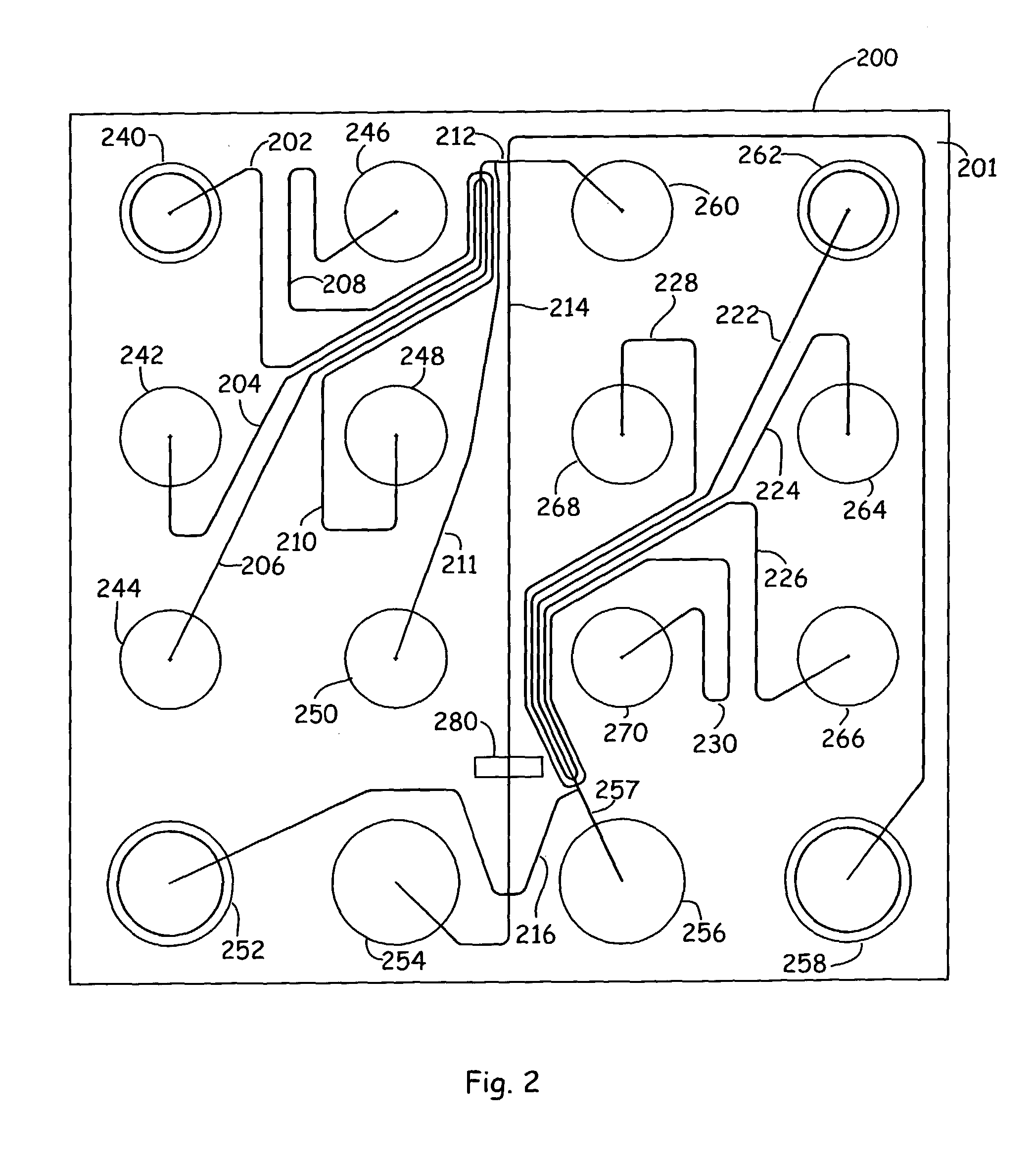
[0057] In order to accurately extract a separated component of a particular size, first, an appropriate standard
sizing ladder is added to one of the sample wells 240-248 and run through the separation channel 214. The
sizing ladder enables the size of unknown fragments to be determined. A commonly used standard is restricted
wild type lambda DNA
cut with
HindIII which gives twelve fragments with a good size range. In addition,
sizing ladders can be made by ligating DNA fragments together to form a series of bands, such sizing ladders being commercially available from Bioventures, Inc. (Murfreesboro, Tenn.), for example. An internal size standard provides accurate and reproducible
size determination and quantification, and eliminates problems associated with run-to-run electrophoretic variability.
[0058] After the sizing ladder sample has been separated and all the bands have been detected at detection window 280 by
detector 304, the
electrode current can be switched to move a first sample into position from one of the sample wells 240-248. Sample material is then drawn into the sample loading channel 212, e.g., by drawing a sample material in fluid out of one of the sample reservoirs 240, 242, 244, 246, or 248 and into sample loading channel 212 electrokinetically by applying a
voltage potential between well 260 and one or more of sample wells 240-248, as is described in U.S. Pat. No. 5,976,336, for example, which was previously incorporated herein by reference in its entirety for all purposes. Alternatively, in the case of a sipper
chip, for example, materials can be moved into sample loading channel by applying a vacuum to reservoir 250 (and / or reservoir 260), whereby the flow of the materials is achieved by applying a pressure differential through the channels, e.g., by applying a vacuum to reservoir 250 and / or by applying a
positive pressure to one of the sample wells 240-248. During the sample loading process, any
separation matrix that has entered the sample loading channel 212 is washed away by the bulk flow of the sample material. Following injection of the sample material through the intersection of channel 212 and separation channel 214, an
electrical current is applied through the length of the separation channel to electrokinetically move the sample material at the intersection into and through the separation channel. In preferred aspects, a slight current is supplied back through the portions of channel 212 that meet with separation channel 214, in order to push back sample material from the intersection. This improves separation efficiencies by eliminating substantial leakage that can contaminate the separation run. As the sample material (e.g., sample material 290 in FIG. 4A) is electrophoresed through the sample matrix in the separation channel, it is separated into fractions, e.g., fractions 292 in FIGS. 4C-D, that differ based upon their molecular weights.
[0062] Then, when such separated fragment of a particular size of interest is detected (based on comparisons to the sizing curve which is generated by the computer), the computer includes
programming to instruct the operation of the flow controller 302 to direct fluid movement through the collection conduit 216 in accordance with the user specified instructions. In controlled electrokinetic transport, the separated component of interest (e.g., fragment 293 in FIGS. 4C-D) is moved into the collection conduit by applying a
voltage gradient along the path of
material flow, e.g., by applying a
voltage potential between electrodes positioned in well 252 and one of wells 262-270. In order to ensure that only fragment 293 is shunted into the collection conduit 216 (and that there is no cross-
contamination from one or more of the other fragments 292), the
voltage gradient applied to separation conduit 214 generally must be tightly regulated, e.g., temporarily stopped and then reinitiated only after fragment 293 reaches one of collection wells 262-270, to avoid inadvertent
shunting of other separated components 292 into the collection conduit during this injection period. Where the material
path length to any of collection wells 262-270 is relatively long, as it is, for example, for well 262 (which is fluidly coupled to collection conduit 216 via relatively long channel segment 222), this
delay in placing the separation conduit in an "off" mode can be appreciable, which can significantly decrease the throughout of the
system (particularly where multiple samples are run through the device).

