Flow measuring apparatus using tube waves and corresponding method

a flow measurement and tube wave technology, applied in the direction of volume/mass flow measurement, measurement devices, instruments, etc., can solve the problems of limiting the scope of many methods suitable for liquid-only flows, affecting the accuracy of flow measurement, so as to reduce the frequency band of interest of flowmeters, reduce the amount of potential reflection of original wave signals, and reduce the invasion of ambient noise

Active Publication Date: 2010-08-05
SCHLUMBERGER TECH CORP
View PDF12 Cites 23 Cited by
  • Summary
  • Abstract
  • Description
  • Claims
  • Application Information

AI Technical Summary

Benefits of technology

[0027]In case the upstream or downstream transceivers are arrays of transceivers, noise in the frequency band of interest of the flowmeter can be reduced by introducing delays into the wave emission of the respective array elements. The delay can be tuned to suppress by destructive interference the wave signals traveling out of the flowmeter section. Whilst this embodiment does not reduce the invasion of ambient noise into the flowmeter section as the filters above do, it reduces the amount of potential reflection of the original wave signals. These reflections as being exactly in the frequency range of interest can contribute disproportionately to noise which distorts the actual measurement.

Problems solved by technology

Thus, the determination of flow rate for a two-phase flow can be significantly more complex than for a single phase flow, and usually attempts are made to mix the flow before flow rate measurements are taken.
The present of gas poses further problems when establishing exact flow-rates and hold-ups.
Gas usually has properties significantly different from oil and water, thus limiting the scope of many methods suitable for liquid-only flows.
The drawback of such a flowmeter is that it is only applicable to near single-phase flows.
The main drawback is the need to choke the flow with a quick closing valve, which is often not permitted for down-hole applications such as the DST.
Second, discontinuous or non-uniform structures in the multi-phase flow produce acoustic signatures that can be detected by the fiber-optical sensor as they pass the sensor.
The drawbacks with this flowmeter are: first, the passive acoustic method is not reliable if the flow is nearly single-phase, as it sometimes is in down-hole applications; second, the travel velocity of the non-uniform structures, from our experience in down-hole flow meters, cannot be always equalized to the homogeneous velocity, particularly at low velocities and in highly deviated wells.
The cross-correlation based method also will not work in single-phase flows where the non-uniform structures do not exist.

Method used


Image

  • Flow measuring apparatus using tube waves and corresponding method
  • Flow measuring apparatus using tube waves and corresponding method
  • Flow measuring apparatus using tube waves and corresponding method

Examples


Embodiment Construction

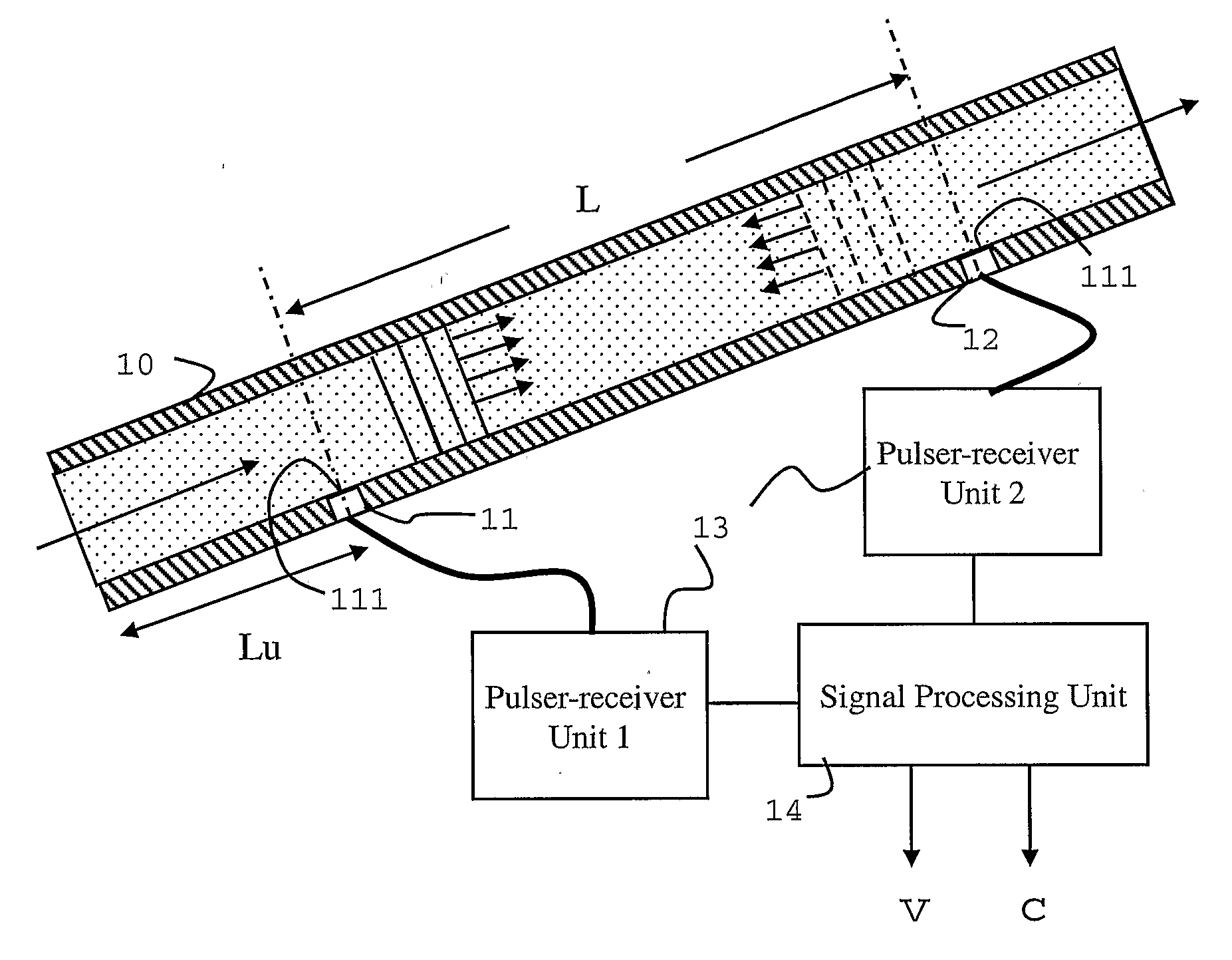
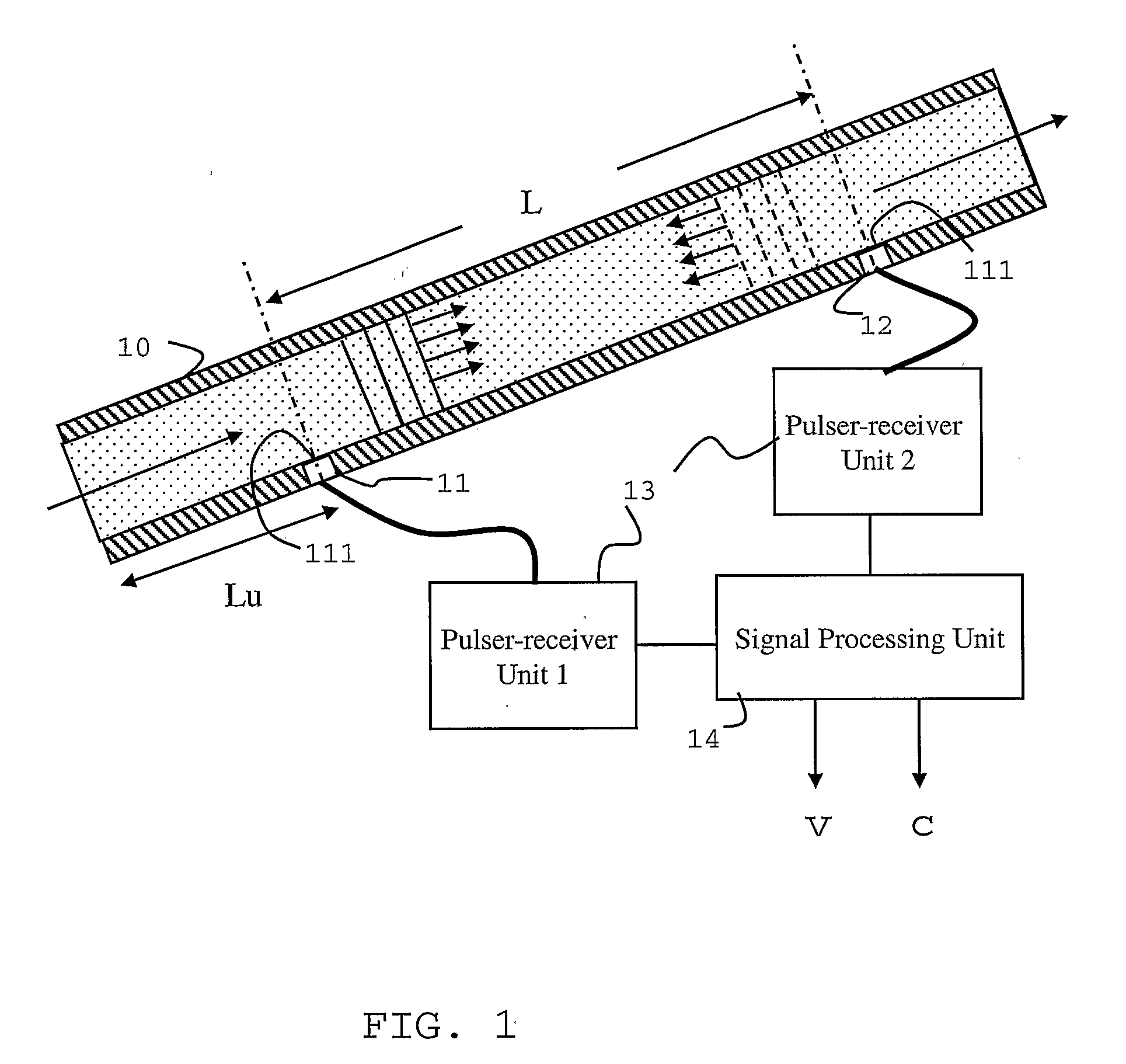
[0039]A first embodiment of the invention is shown in FIG. 1. At least two acoustic transceivers 11,12 (a single device used as either the transmitter or the receiver) are mounted on a flow-conveying pipe 10. The two acoustic transceivers 11, 12 are separated by a known, distance, denoted L. The two acoustic transceivers 11,12 are mounted such that acoustic energy can be emitted directly into the fluid in the pipe 10. Thus, in this embodiment the active sound-emitting faces 111 of the transceivers are in direct contact with fluid in the pipe. The active elements are acoustically isolated from the surrounding pipe wall, so that the acoustic energy generated by a transmitter 11,12 is mostly coupled into the fluid in the pipe bore, rather than into the wall of the pipe.

[0040]The acoustic isolation can be readily achieved using a material that provides a significant impedance step to either the material of the transducer or the pipe wall material or both. A rubber or other polymeric mat...


PUM


Abstract

Methods of measuring flow properties and flowmeters having an upstream transceiver and a downstream wave transceiver, each positioned with a wave emitting surface exposed to a fluid flowing in a conduit are described, the transceiver being separated by a length L along the conduit and adapted to receive wave signals traveling in flow direction and opposite to the flow direction, respectively, and an electronic processor for extracting from travel time measurements of the wave signals flow characterizing parameters, the transceivers being adapted to generate tube waves, particularly in the audible frequency range, in the conduit and used to determine the travel time of the tube waves between the upstream transceiver and the downstream wave transceiver.

Description

[0001]The present invention relates to an apparatus and method for the determination of one or more characteristics of a flowing fluid. In particular, the present invention is concerned with the determination of the flow rate of a flowing fluid, such as a fluid which may be encountered in hydrocarbon well boreholes.BACKGROUND OF THE INVENTION[0002]Knowledge of the flow rate of fluid in hydrocarbon well boreholes is important for monitoring and controlling fluid movement in the well and reservoir. Typically, in such hydrocarbon wells, the fluid flowing along the borehole includes a hydrocarbon (e.g. oil) and water. Each zone of the reservoir may have a valve to control the fluid inlet from that zone. By monitoring the flow rates of oil and water coming from each zone, the flow rate of oil can be optimised by control of the valves. In this way, the water cut may be minimised for example.[0003]A flow meter installed in piping in a hydrocarbon well borehole is subject to several design ...

Claims


Application Information

Patent Timeline
Patent Type & Authority Applications(United States)
IPC IPC(8): G01F1/66G01F1/7082
CPCG01F1/66G01F1/662G01F1/74G01F1/712G01F1/7082
Inventor HUANG, SONGMINGODDIE, GARY
Owner SCHLUMBERGER TECH CORP
Why Eureka
Try Eureka