Retractable hitch-ball mechanism

a hitch-ball mechanism and retraction technology, which is applied in the direction of towing devices, vehicle components, transportation and packaging, etc., can solve the problems of affecting the ability of users to shovel loose materials, damage to sheet goods, and difficulty in vertical adjustment of the hitch-ball member. , to achieve the effect of facilitating vertical adjustment of the hitch-ball member

Inactive Publication Date: 2010-08-17
YOUNGS PRODS
View PDF26 Cites 6 Cited by
  • Summary
  • Abstract
  • Description
  • Claims
  • Application Information

AI Technical Summary

Benefits of technology

[0009]In order to overcome the above-stated problems and limitations, and to achieve the noted advantages, there is provided a retractable hitch-ball mechanism having a mounting frame assembly adapted to fixedly secure an adjustment-control mechanism to the bed frame of a pickup truck. The adjustment-control mechanism generally includes a housing, a hitch ball member, and a drive plate. The drive plate is selectively actuated from a remote location by a linkage. The housing includes a tubular sleeve defining a longitudinal axis. The tubular sleeve includes a pair of opposed arcuate slots that are orientated in a generally parallel-spaced relation to the longitudinal axis. The hitch ball member is slidably disposed within the tubular sleeve and moveable therein between an extended use position and a retracted storage position. The drive plate includes a profile with a distal landing, a proximal landing, and an inclined edge intermediate the distal and proximal landings. Additionally, the drive plate is received in and cooperates with a capture groove located in a lower portion of the hitch ball member for facilitating vertical adjustment of the hitch ball member. Typically, the drive plate is received by the pair of opposed arcuate slots and is laterally moveable therein. The linkage includes an end mechanically coupled to the drive plate and a user-engageable end opposed thereto. The user-engageable end extends to a control location that is spaced from the hitch ball member and which provides a user with selective operation of the drive plate.
[0010]The hitch ball member is moveable into different positions, as facilitated by the adjustment-control mechanism. In one embodiment, these positions correspond with movement of the hitch ball member between the following: an operative position, where at least a portion of the capture groove is engaged with the distal landing, and a retracted position, where at least a portion of the capture groove is engaged with the proximal landing. In addition, the drive plate is laterally moveable between a first position and second position, whereby the inclined edge engages the hitch ball member, thereby facilitating its vertical movement within the tubular sleeve.

Problems solved by technology

However, by virtue of their arrangement, bumper pulled trailers are limited to a relatively small size and have severe load restrictions.
While hitch-ball mounting designs of this type can be found, a problem associated with this hitching arrangement is that it often requires the presence of an upwardly projecting hitch-ball mounted to the middle of the floor of the bed.
This type of arrangement presents a problem in the event a user of the vehicle desires to lay large, flat, sheet goods in the bed.
In that situation, the hitch-ball prevents the sheet goods from laying flat in the bed and, coincidentally, can damage the sheet goods.
Additionally, if the user of the vehicle fills the bed with loose material, such as dirt or gravel, and attempts to shovel the loose material out, the upwardly projecting hitch member often interferes with the user's ability to shovel the loose material.
However, these arrangements have inherently created additional problems for the user of the vehicle.
In one situation where the hitch-ball is removable, the hitch-ball is often misplaced and, eventually, lost.
Additionally, these arrangements are costly and involve complex moving parts that easily become contaminated and frequently require repair and cleaning.

Method used


Image

  • Retractable hitch-ball mechanism
  • Retractable hitch-ball mechanism
  • Retractable hitch-ball mechanism

Examples


Embodiment Construction

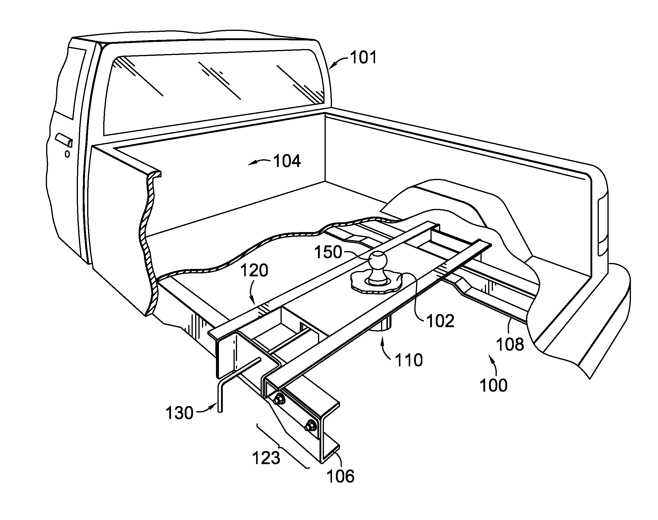
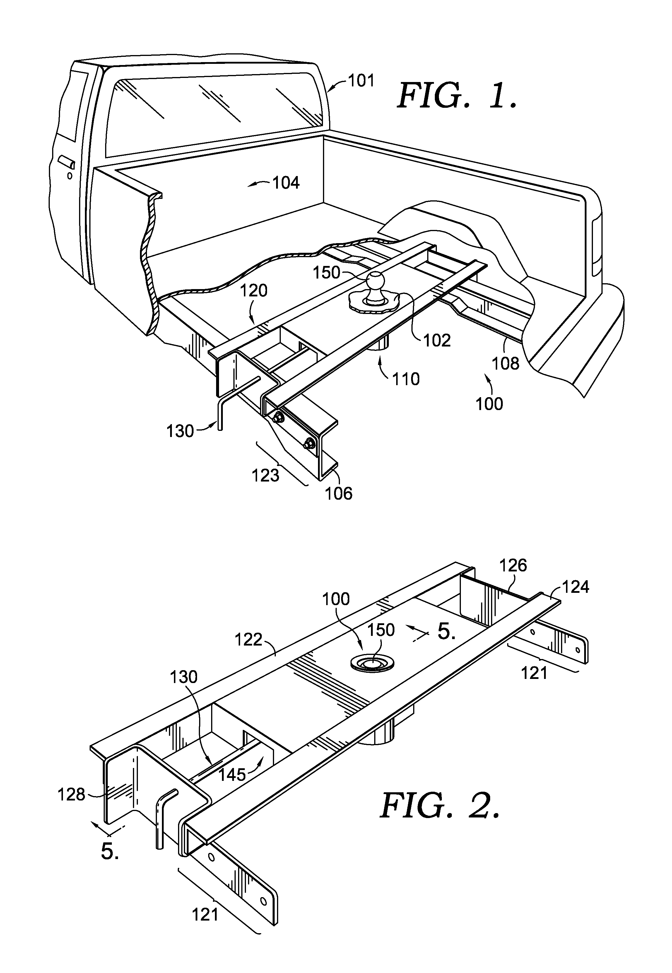
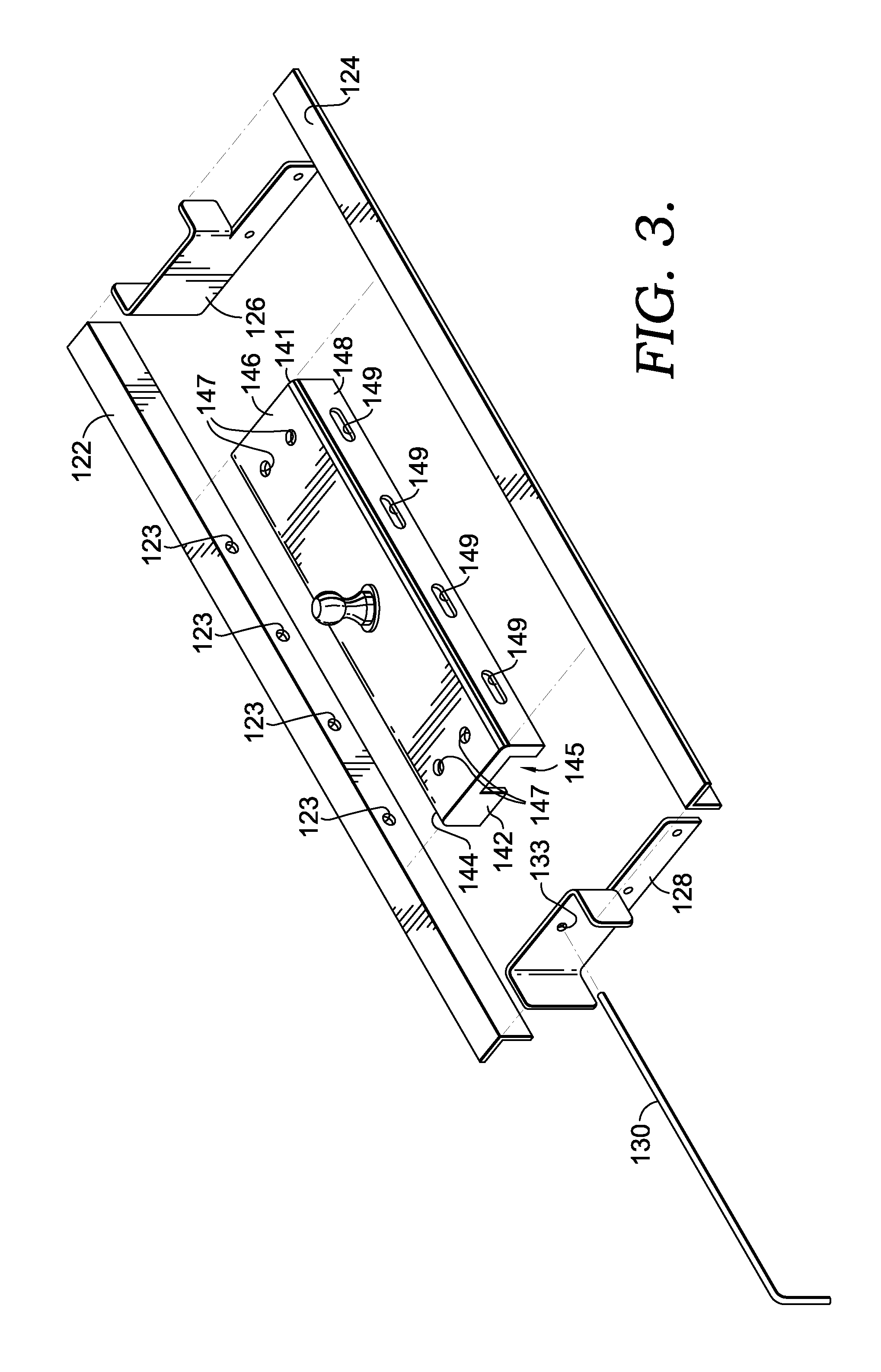
[0026]Referring now to the drawing in greater detail and initially to FIG. 1, the present invention is directed to an retractable hitch-ball mechanism (hereinafter the “mechanism”), which is shown and designated generally by reference numeral 100 and constructed in accordance with an embodiment of the present invention. The mechanism 100 broadly includes, an adjustment-control mechanism 110 that includes a hitch ball member 150, a mounting-frame assembly 120, and an activation linkage 130. The hitch ball member 150 is selectively moveable into different positions by way of the adjustment-control mechanism 110, in a manner discussed in more detail below with reference to in FIGS. 5-7.

[0027]The vertical position of the hitch ball member 150 changes with lateral movement of the linkage 130. Lateral movement of the linkage 130 moves the hitch ball member 150 from a use position, in which the hitch ball member 150 extends upwardly through a floor 102 of a bed 104 of a truck 101, to a ret...


PUM


Abstract

This invention is related to a retractable hitch-ball mechanism adapted for coupling to a frame of a vehicle, such as a pickup truck. The mechanism includes a support structure that is secured to the frame by a mounting-frame assembly, a housing having a tubular sleeve, a hitch ball member slidably disposed within the tubular sleeve, a drive plate, and a linkage coupled to the drive plate at one end and having a user-engageable portion at an opposed end. Upon a user exerting force on the opposed end, the hitch ball member is selectively movable between an extended use position, wherein a portion of the hitch ball member extends upwardly from the tubular sleeve, and a retracted storage position, wherein the ball portion is substantially hidden. Selective adjustment is facilitated by an inclined edge on the drive plate that slidably engages at least a portion of the hitch ball member.

Description

CROSS-REFERENCE TO RELATED APPLICATIONS[0001]Not applicable.STATEMENT REGARDING FEDERALLY SPONSORED RESEARCH OR DEVELOPMENT[0002]Not applicable.BACKGROUND OF THE INVENTION[0003]This invention relates to ball-style hitches located in the bed of a towing vehicle, such as a traditional pickup truck, that engage a releasable coupling on the tongue of a trailer. More particularly, this invention relates to a retractable hitch-ball mechanism that allows a user to selectively move a hitch ball from an operative position, in which a ball portion projects upwardly above the bed, to a retracted position, in which the ball portion is hidden when it is not needed for towing, thereby permitting the user to make full use of the truck's bed.[0004]The most common method of hooking a trailer to a vehicle for towing is attaching the trailer to a hitch-ball that is mounted on or near the vehicle's rear bumper. However, by virtue of their arrangement, bumper pulled trailers are limited to a relatively ...

Claims


Application Information

Patent Timeline
Patent Type & Authority Patents(United States)
IPC IPC(8): B60D1/54
CPCB60D1/06B60D1/54
Inventor DICK, BERNARD L.
Owner YOUNGS PRODS
Why Eureka
Try Eureka