
Lamp unit and projector employing same

a technology of projector and lamp unit, which is applied in the field of lamp unit, can solve the problems of difficult to obtain a sufficient cooling capability and difficult to perform such local cooling with a fan, and achieve the effects of reducing the speed of air, reducing the cross-sectional area of the fluid passage forming member, and minimizing the reduction

Inactive Publication Date: 2010-08-17
NEC DISPLAY SOLUTIONS LTD
View PDF12 Cites 11 Cited by
  • Summary
  • Abstract
  • Description
  • Claims
  • Application Information

AI Technical Summary

Benefits of technology

[0007]It is an exemplary feature of the present invention to provide a lamp unit which will solve the above and other exemplary problems and which is capable of applying cooling air at a sufficient speed highly accurately to a desired region of a lamp.
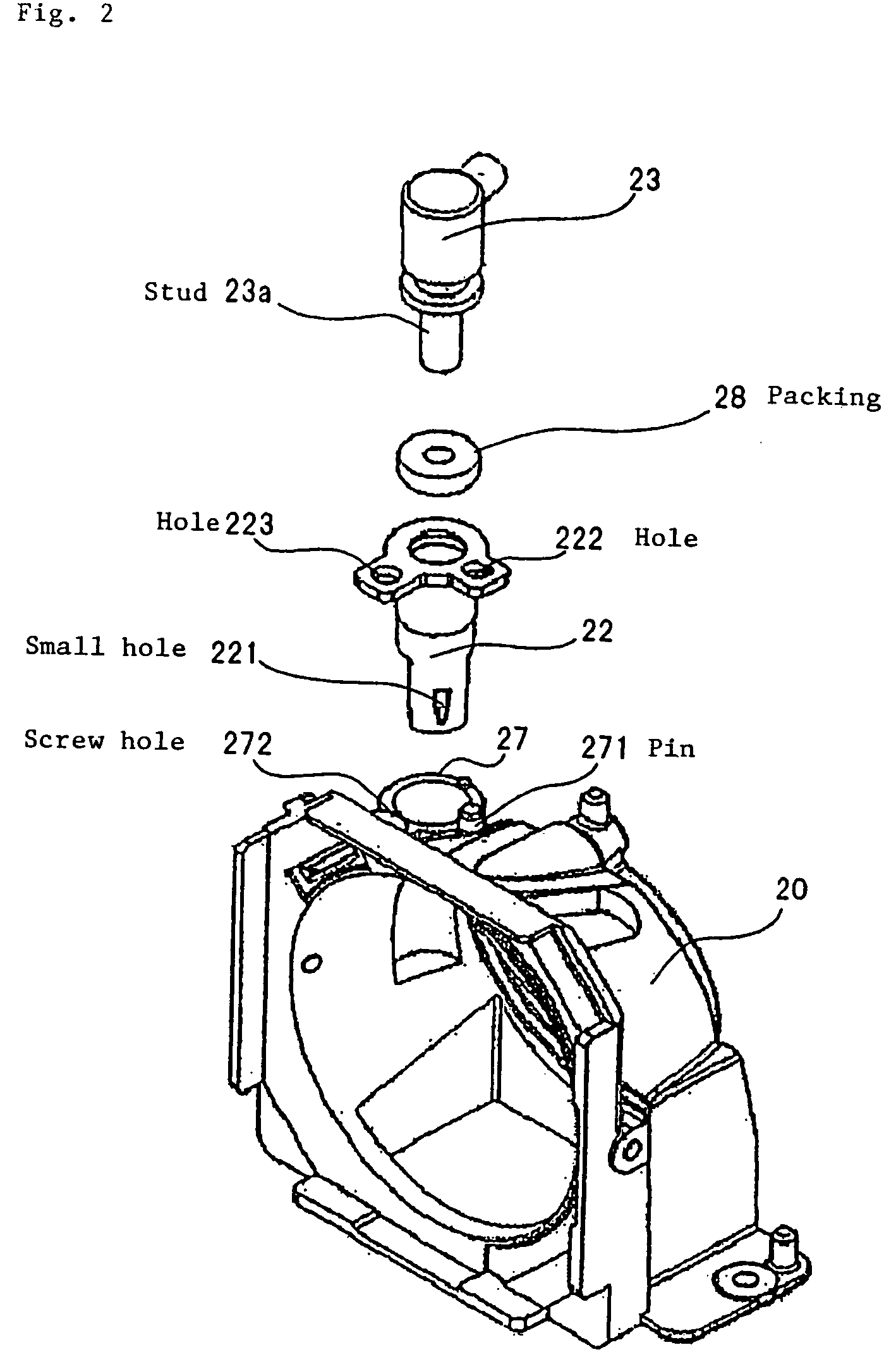
[0010]In the present invention, furthermore, the reflector with the lamp mounted therein is held by the reflector holder, and the ejector member is fixed to the reflector holder. Thus, both the lamp and the ejector member are positioned with respect to the reflector holder. Since the same member is used as a reference for positioning the lamp and the ejector member, the positional relationship between the lamp and the ejector member is set with high accuracy, and the cooling air discharged from the small hole of the ejector member can be applied highly accurately to a desired area of the lamp.
[0012]According to the present invention, the air supply member is inserted in the ejector member to realize an exchangeable unit (e.g., modular) structure. In such a structure, the size of the cross section of the fluid passage at the insertion member is greater than the outer profile of the air supply member. If the fluid passage cross-sectional area is the same as the fluid passage cross-sectional area at the insertion member throughout the fluid passage forming member, then the compressed air supplied from the air supply member is introduced into the fluid passage as a large space, whereupon the air suffers a pressure loss, resulting in a reduction in the speed of the air discharged from the small hole. The fluid passage cross-sectional area of the fluid passage forming member can be reduced advantageously to minimize a reduction, caused by the pressure loss, in the speed of the air discharged from the small hole. According to the present invention, since the fluid passage cross-sectional area at the distal end of the ejector member is smaller than the fluid passage cross-sectional area at the insertion member, the speed of the air discharged from the small hole is increased.
[0013]According to the present invention, as described above, inasmuch as the cooling air is discharged at a sufficient speed from the small hole of the ejector member, and the cooling air is applied highly accurately to a desired area of the lamp (e.g., a high-pressure mercury lamp or the like), the lamp can be maintained at an appropriate temperature. Therefore, the lamp is prevented from becoming clouded and blackened (e.g., due to mercury deposition or anode spot on the inner wall surface of the lamp), and, as a consequence, has a longer service life and has higher reliability than heretofore.

Problems solved by technology

However, it is difficult to obtain a sufficient cooling capability only when the air flow (cooling air flow) produced by introducing the cooling air from the fan into the reflector impinges upon the lamp.
It is difficult to perform such local cooling with a fan.

Method used


Image

  • Lamp unit and projector employing same
  • Lamp unit and projector employing same
  • Lamp unit and projector employing same

Examples


Embodiment Construction

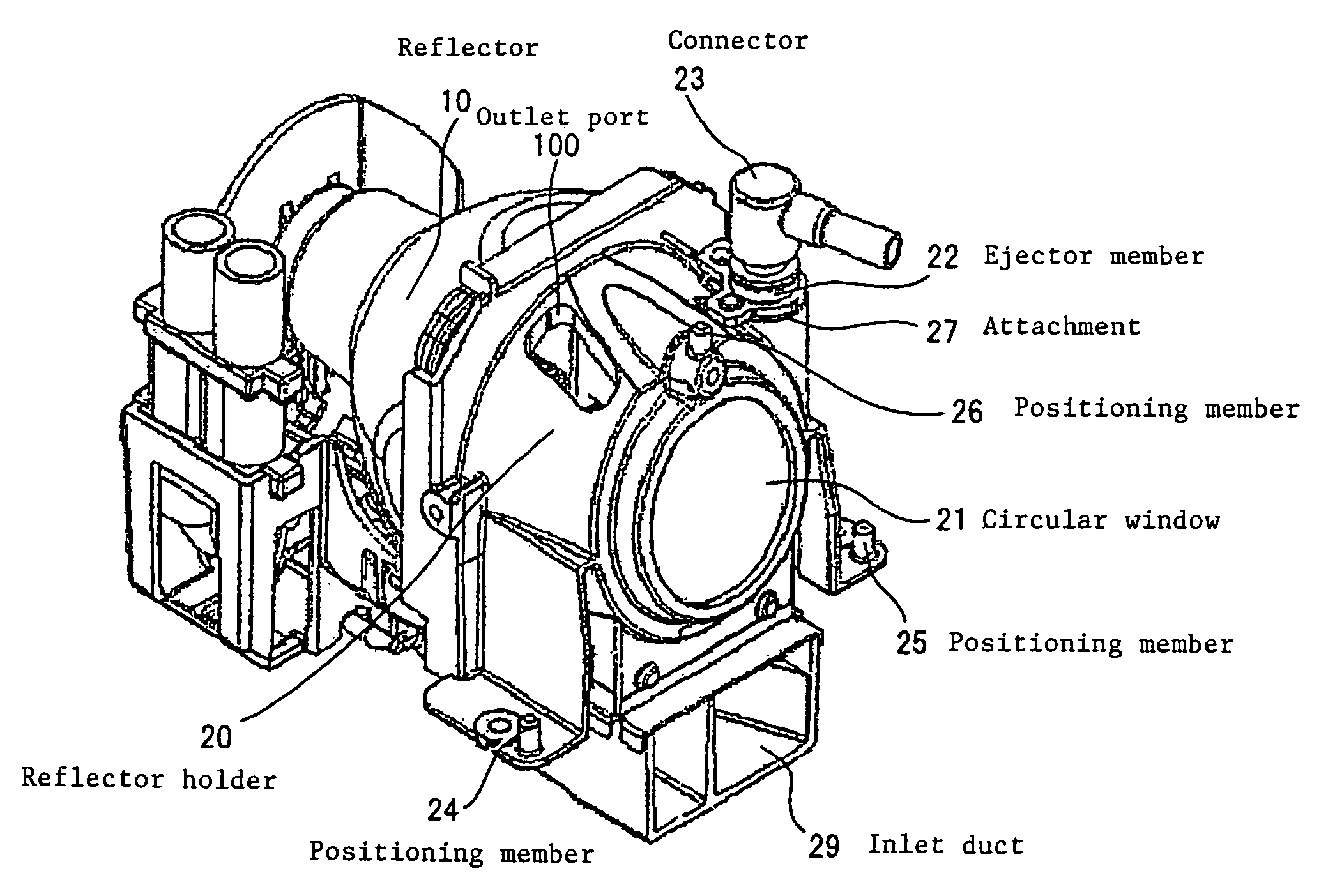
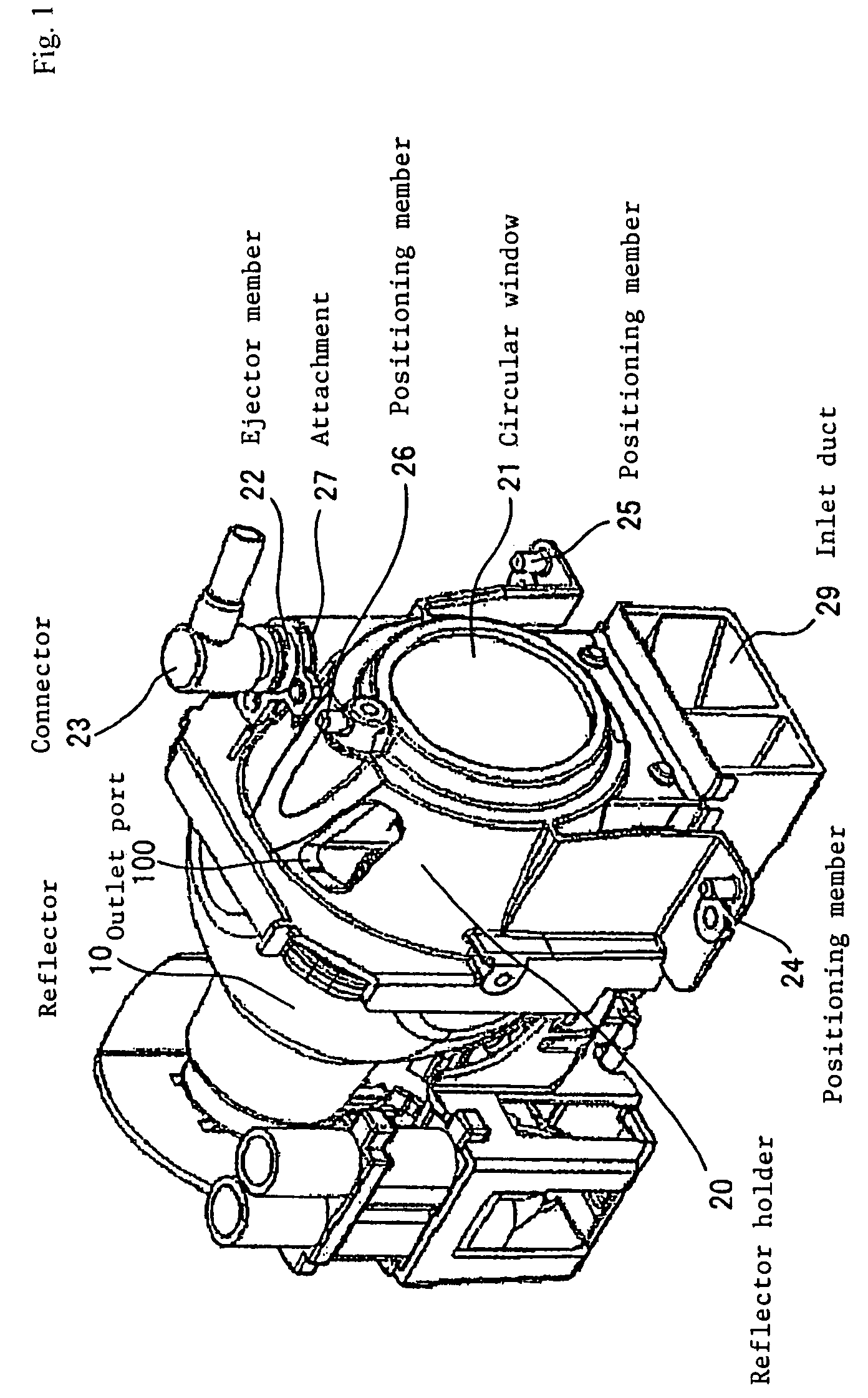
[0024]FIG. 1 is a perspective view of a lamp unit according to an exemplary embodiment of the present invention. As shown in FIG. 1, the lamp unit, which is to be incorporated in a projector, includes reflector 10 including a lamp and reflector holder 20 holding the open end of reflector 10. Reflector 10 has a concave reflecting surface, e.g., a reflecting surface formed as a paraboloid of revolution, with the lamp located at the focal point thereof. Light from the lamp is emitted directly from the opening or reflected by the reflecting surface and then emitted from the opening in a certain direction.

[0025]Reflector holder 20 is in the form of a cup covering the open end of reflector 10, and has circular window 21 for passing therethrough the light emitted from the open end of reflector 10. Window 20 is made of a transparent material (e.g., such as glass or resin) having such properties that the material passes therethrough light in a wavelength range used in the device which incorp...


PUM


Abstract

A lamp unit includes a reflector with a lamp mounted therein, a reflector holder holding the reflector, and an ejector member fixed to the reflector holder, for ejecting air to cool the lamp, the ejector member including an insertion member with a tubular stud inserted therein for supplying compressed air, a fluid passage forming member having a fluid passage for being supplied with air from the stud, and a hole defined in a distal end of the ejector member.

Description

TECHNICAL FIELD[0001]The present invention relates to a lamp unit including a cooling mechanism.BACKGROUND ART[0002]Generally, projectors include a cooling device for cooling an installed lamp. A fan is widely used as the cooling device.[0003]JP-A No. 2003-215706 discloses a lamp unit including a reflector with a lamp located at its focal point and a holder for holding the open end of the reflector. The open end of the reflector is covered with a transparent plate for preventing fragments from being scattered around in the event that the lamp blows up.[0004]The holder has an inlet port for introducing air into the reflector and an outlet port for discharging air from the reflector. When cooling air from a fan disposed outside of the reflector is introduced from the inlet port into the reflector and air in the reflector is discharged from the outlet port, an air flow (cooling air flow) is developed in the reflector, and impinges upon the lamp to cool the lamp.DISCLOSURE OF THE INVENT...

Claims


Application Information

Patent Timeline
Patent Type & Authority Patents(United States)
IPC IPC(8): G03B21/16F21Y101/00
CPCF21V29/02G03B21/16F21V29/67
Inventor NISHIMURA, YOSHIFUMITAKAMATSU, HIROAKI
Owner NEC DISPLAY SOLUTIONS LTD
Learn More