Airbag cushion

a technology for airbags and cushioning, which is applied in the direction of pedestrian/occupant safety arrangements, vehicular safety arrangements, vehicle components, etc., can solve the problems of airbag cushion deployment kinetic energy very great, passenger injury due to airbag cushion, airbag cushion may be difficult to penetrate the panel of the driver seat or the passenger seat and then deploy

Inactive Publication Date: 2010-05-25
HYUNDAI MOBIS CO LTD
View PDF29 Cites 16 Cited by
  • Summary
  • Abstract
  • Description
  • Claims
  • Application Information

AI Technical Summary

Benefits of technology

[0052]First, an enough pressure to penetrate the panel of a driver's seat or a passenger seat in which the airbag cushion is mounted can be secured.
[0053]Second, when a passenger is seated in a vehicle seat abnormally, the passenger can be prevented from suffering injury due to the deployment of the airbag cushion.
[0054]Third, a sufficient speed at which the airbag cushion is deployed can be secured.
[0055]Fourth, elastic force enough to absorb shock generated when the airbag cushion is deployed can be secured.
[0056]Fifth, it is possible to control a pressure generated when the airbag cushion is deployed, which can satisfy various conditions through some modifications.
[0057]Sixth, means for controlling a pressure generated when the airbag cushion is deployed is disposed outside the airbag cushion. Accordingly, the process is convenient, hindrance to internal structures can be prevented, and reliability in pressure control of the airbag cushion can be secured.

Problems solved by technology

However, a pressure when the airbag cushion is deployed is very high and, therefore, the amount of kinetic energy when the airbag cushion is deployed is very great.
If the kinetic energy is transferred to the passenger without change, the passenger can suffer injury due to the airbag cushion.
However, if the pressure of the airbag cushion is too lowered, the airbag cushion may be difficult to penetrate the panel of the driver seat or the passenger seat and then deploy.
In this case, the airbag cushion may not be deployed at an appropriate time because a speed at which the airbag cushion is deployed is too slow.

Method used


Image

  • Airbag cushion
  • Airbag cushion
  • Airbag cushion

Examples


first embodiment

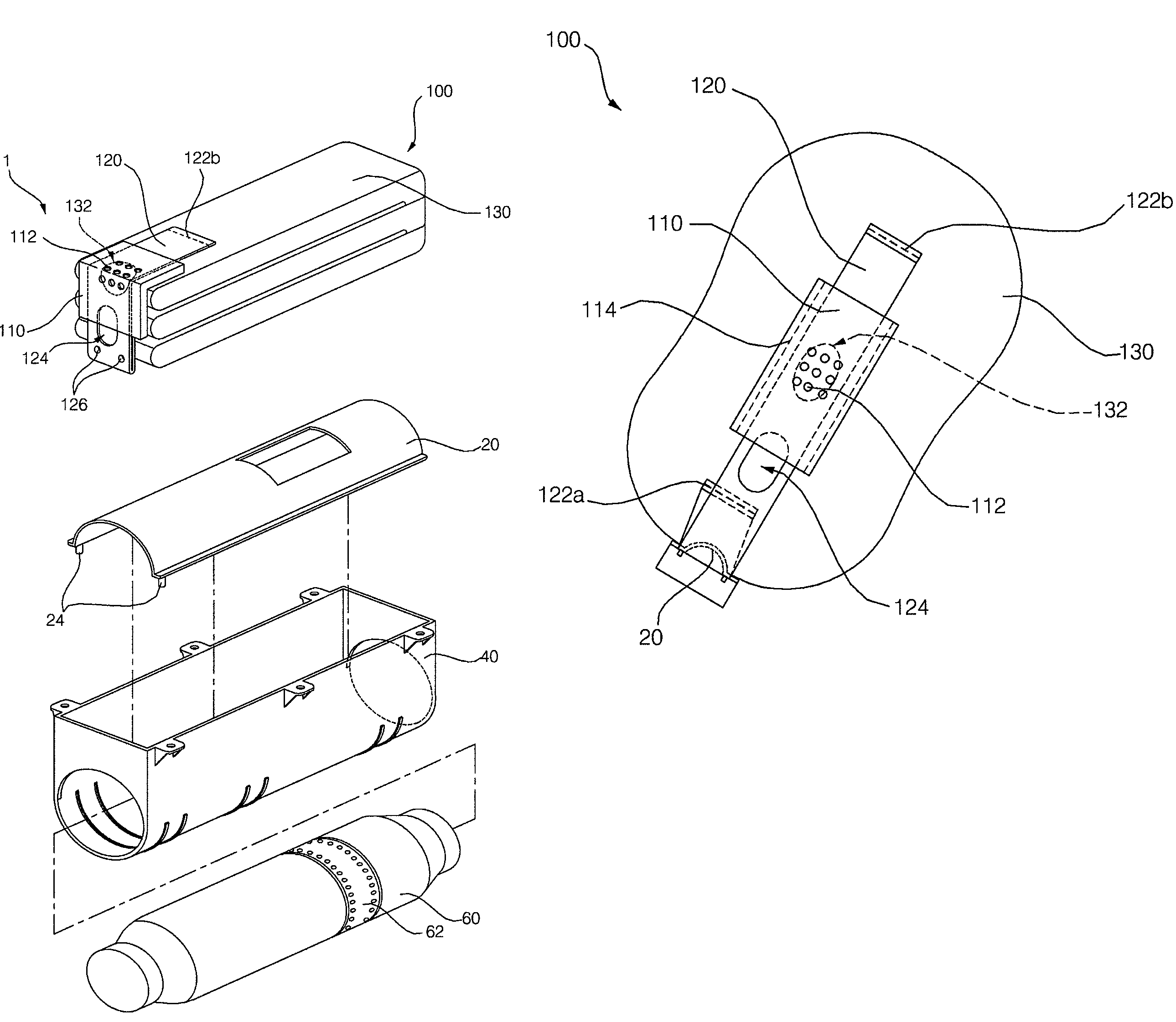
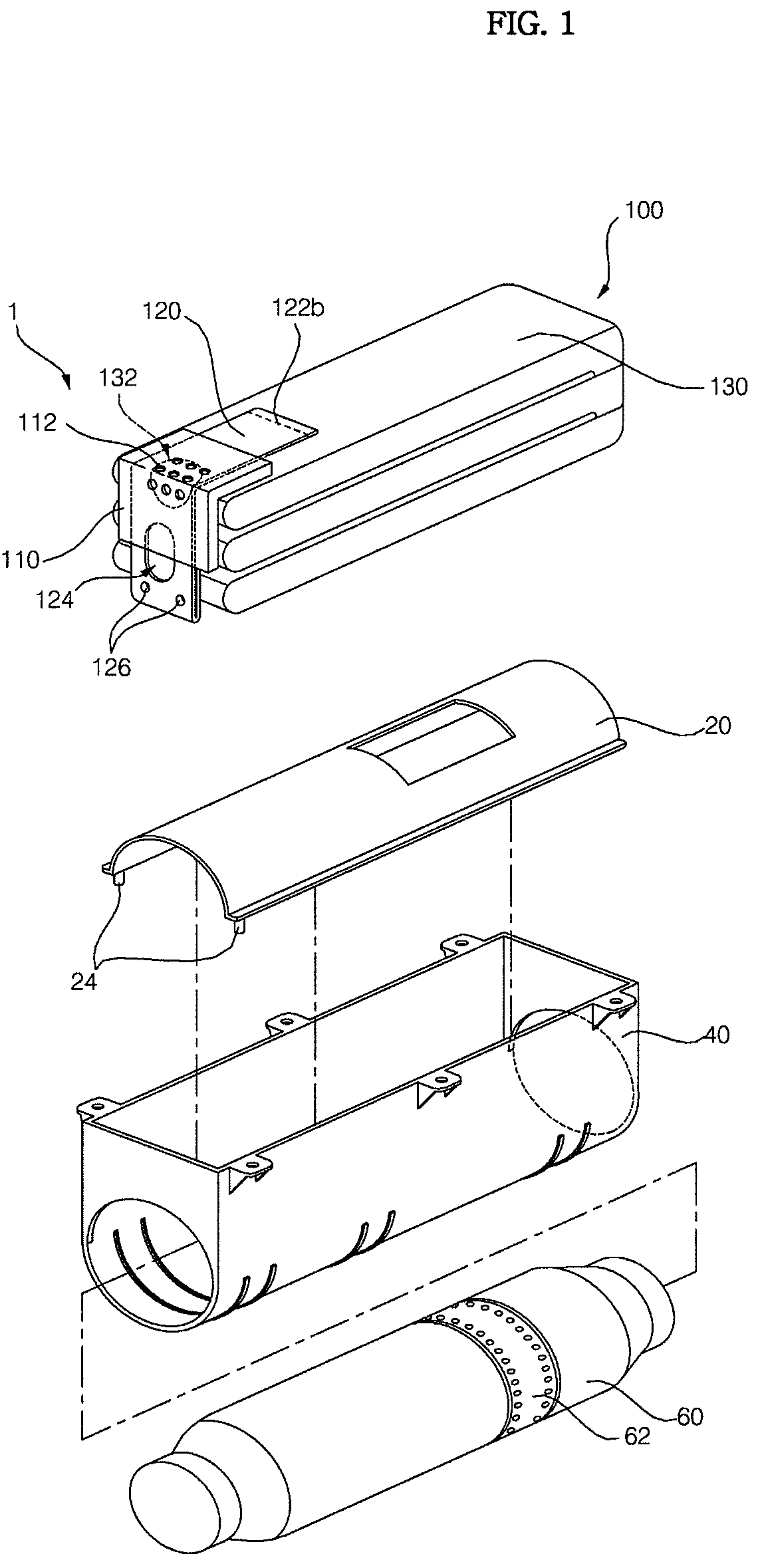
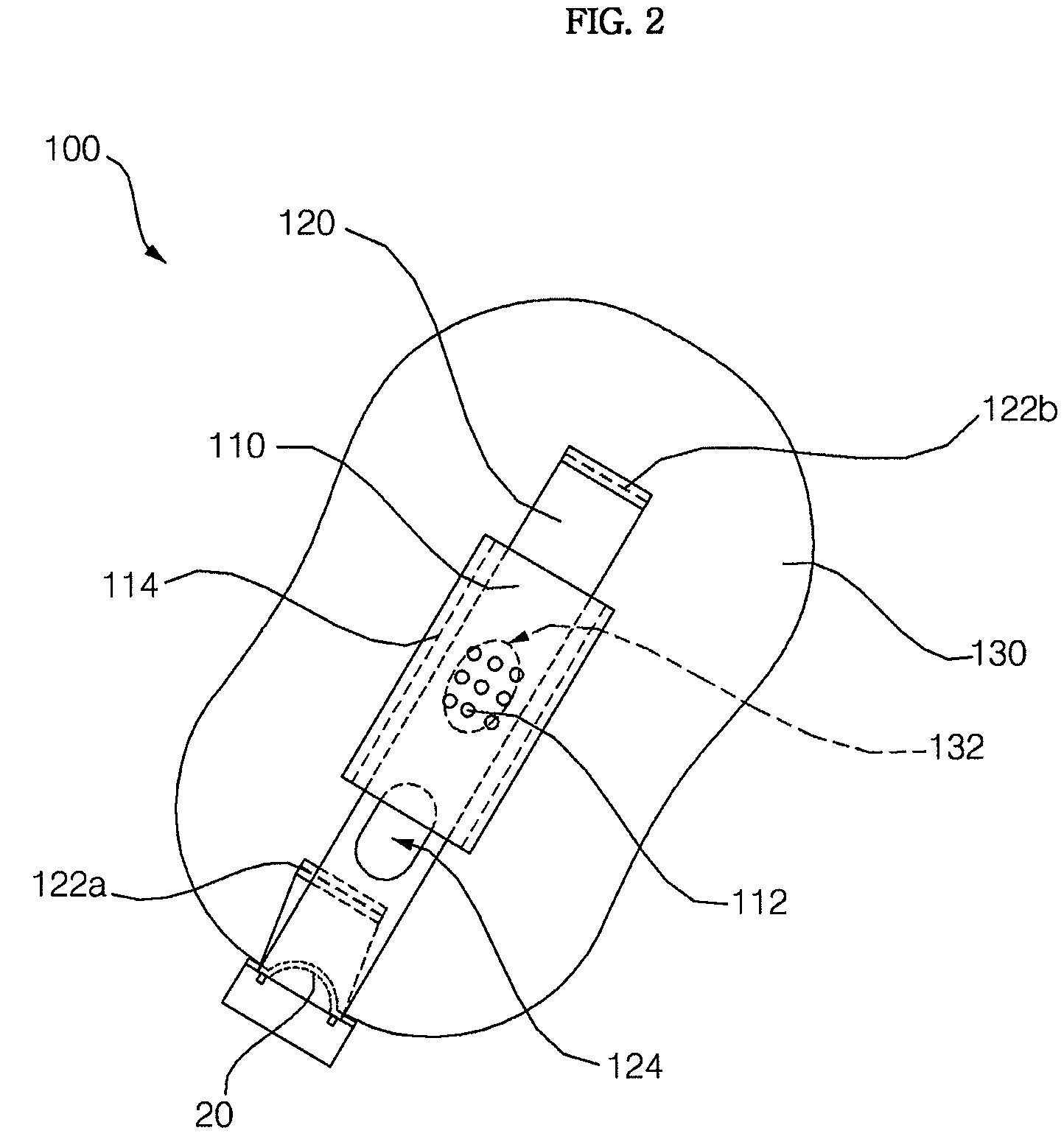
[0023]the present invention is described below with reference to FIGS. 1 to 4.

[0024]An airbag module 1 of the present embodiment includes an airbag cushion 100 that is deployed at a high speed by an incoming gas when a vehicle crashes, an inflator 60 for supplying the gas of a high pressure, which is caused by explosive power due to a chemical reaction when the vehicle crashes, to the airbag cushion 100 through a gas discharge unit 62, thereby deploying the airbag cushion, a housing 40 for receiving the inflator 60, a cushion support 20 which supports the airbag cushion 100 and has clamping pins 24 latched to clamping holes 126 formed in a sliding belt 120, and so on.

[0025]The airbag cushion 100 includes a deployment portion 130, a belt guider 110, and a sliding belt 120. The deployment portion 130 is deployed by the pressure of the gas supplied from the inflator 60 and has a pressure control vent hole 132 formed therein. The belt guider 110 is attached to the deployment portion 130...


PUM


Abstract

The present invention relates to an airbag cushion for protecting a driver and passengers when a vehicle crashes, wherein the sliding bent is guided into a belt guider and slides between a deployment portion and the belt guider, when the deployment portion is deployed. The sliding belt slides between the deployment portion and the belt guider in such a manner that before the deployment portion is deployed, the sliding belt clogs the first vent holes, when the deployment portion is partially deployed, the second vent hole forms a flow channel together with the first vent holes so that the gas is discharged along the flow channel through the first vent holes, and when the deployment portion is fully deployed, the sliding belt clogs the first vent holes so that the gas is not discharged through the first vent holes.

Description

[0001]This Nonprovisional application claims priority under 35 U.S.C. §119(a) on Patent Application No. 10-2007-0130347 filed in Korea on Dec. 13, 2007, the entire contents of which are hereby incorporated by reference.BACKGROUND OF THE INVENTION[0002]1. Field of the Invention[0003]The present invention relates to an airbag cushion for protecting a driver and passengers when a vehicle crashes.[0004]2. Discussion of Related Art[0005]In recent years, consumers attach importance to the safety of a vehicle as well as the performance or design of the vehicle when selecting the vehicle. In line with this trend, vehicle manufacturers set an important goal for technology development in order to secure the safety of a vehicle. In this technology development circumstance, an airbag module has recently been in the spotlight of means for improving the safety of passengers when a vehicle collides. Active research has been done in the airbag module. In recent years, there is a tendency that the a...

Claims


Application Information

Patent Timeline
Patent Type & Authority Patents(United States)
IPC IPC(8): B60R21/239
CPCB60R21/2338B60R21/239B60R2021/23386B60R2021/23382B60R21/276
Inventor LEE, JUNG SUKIM, YEON KYEONG
Owner HYUNDAI MOBIS CO LTD
Why Eureka
Try Eureka