
Spray ejector device and methods of use

a technology of ejector device and spraying nozzle, which is applied in the direction of lighting and heating apparatus, combustion type, separation process, etc., can solve the problems of stroke victims, droplets to land on eyelids, noses or other parts of the face, elderly also often lose hand coordination,

Inactive Publication Date: 2013-11-14
EYENOVIA
View PDF6 Cites 50 Cited by
  • Summary
  • Abstract
  • Description
  • Claims
  • Application Information

AI Technical Summary

Benefits of technology

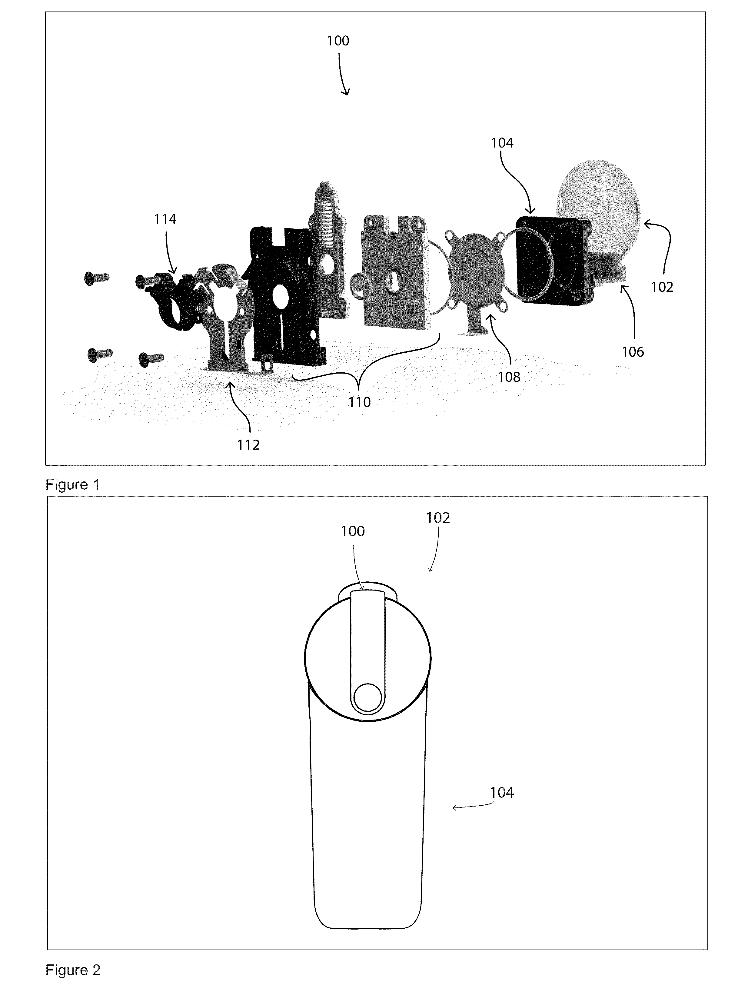
The present disclosure relates to an ejector device that can deliver a consistent and repeatable high percentage of fluid in the form of droplets. The device includes a housing, a reservoir, a fluid loading plate, and an ejector mechanism. The fluid loading plate provides fluid to the ejector mechanism, which ejects a stream of droplets through an opening. The device can be placed in a parallel arrangement with the ejector mechanism to provide fluid to its rear ejection surface. The ejector device is also capable of ejecting a stream of droplets even when tilted or placed in an upright position. The reservoir is a collapsible and flexible container, which can expand to accommodate gas within the volume and prevent leaks. The ejector device also includes an auto-closing system that reduces crystallization, evaporation, and contamination risk. This system includes a user-activated slide-plate that sealingly engages a gasket or seal and is slidable between an open position and a close position. The slide-plate presses with sufficient pressure against the seal in the closed position.

Problems solved by technology

A major challenge in providing such a device is to provide consistent and accurate delivery of suitable doses and to avoid contamination of the product being delivered.
The application of fluids, as in the case of eye drops, has always posed a problem, especially for children and animals, which tend to blink or jerk at the critical moment of administration, causing the droplet to land on the eyelid, nose or other part of the face.
The elderly also often lose the hand coordination necessary to get the eye drops into their eyes.
Stroke victims have similar difficulties.
In current eye dropper bottles, the pointed applicator tip poses the risk of poking the user in the eye, potentially causing physical damage to the eye, and further, exposing the tip to bacterial contamination due to contact with the eye.
As such, the subject runs the risk of contaminating the medication in the eye dropper bottle and subsequently infecting the eye.
Additionally, a large volume of the medication flows out of the eye or is washed away by the tearing reflex.
As a result, this method of administration is also inaccurate and wasteful.
Moreover, the eye dropper does not provide a satisfactory way of controlling the amount of medication that is dispensed, nor does it provide a way of ensuring that the medication that is dispensed actually lands on the eye and remains on the eye.
Eye droppers also provide no way of verifying compliance by a subject.
Even if after a week of use the eye dropper bottle could be checked for the total volume of medication dispensed, e.g., by weighing the bottle, this does not provide a record of day-to-day compliance.
Also, the poor precision with which eye droppers deliver drops to the eye makes it difficult to determine whether the medication is actually delivered into the eye, even though it may have been dispensed.
The ability of piezoelectric droplet generation systems to eject fluid has conventionally been largely limited by the piezoelectric material properties of the employed ceramic.

Method used


Image

  • Spray ejector device and methods of use
  • Spray ejector device and methods of use
  • Spray ejector device and methods of use

Examples


example 1

Measurement of Differential Pressure Leak Values

[0136]FIG. 9 shows an assembly that allows an assembly of container, fluid loading plate and ejector device to be tested for leakage as the pressure is decreased. The fluid filled container is mounted onto a leak pressure test apparatus which consists of an ampoule retaining mount (1), fluid loading plate (2), which delivers fluid behind the ejector plate (3). The leak pressure test apparatus is placed within a vacuum chamber that is pumped by a mechanical pump suitable for attaining 2.75 psi. At this pressure (2.75 psi) the measured pressure differential between STP (13.23 psi) and the lowest measurable leakage pressure (2.75 psi) is 10.5 psi, or 72.3 kPa. Leakage at this pressure is equivalent to a pressure differential encountered in traveling from sea level to 31,000 feet. FIG. 9 also illustrates an aspect of the container having a Vr greater than zero. Thus, the container provides for expansion of the gas as the ambient pressure i...

example 2

Measurement of Mass Loss Over Time

[0140]FIG. 12 shows the mass loss from an ampoule (reservoir) over time to determine the storage ability of ampoules (reservoirs) of the present disclosure. A series of reservoirs are stored for 72 days and the amount of mass determined. From a total volume of 3.5 ml, a total volume of 50 μl escapes over the time period.

experiment 3

Measurement of Ejection Volume at Different Attitude Angles

[0141]FIG. 13 shows the ejection volume at differing attitude angles over a range of frequencies of a piezoelectric ejector device having either a hard reservoir or a flexible reservoir. The flexible ampoule design provides more consistent ejection of fluid volume over a broader frequency range and fill level.

[0142]Although the foregoing describes various reservoir embodiments by way of illustration and example, the skilled artisan will appreciate that various changes and modifications may be practiced within the spirit and scope of the present application. As used herein, a reservoir may be any object suitable for holding a fluid. By way of example, the reservoir may be made of any suitable material capable of containing a fluid. Reservoirs of the present disclosure may be rigid or flexible and the reservoirs of the present disclosure may further be collapsible. As used herein, collapsible refers to a decrease in volume obt...


PUM


Abstract

An ejector device for ejecting droplets of fluid onto a surface includes an ejector mechanism attached to a fluid reservoir through a fluid loading plate that is configured to pierce the reservoir and channel the fluid to a rear surface of the ejector mechanism by capillary action. The ejector mechanism may have a centro-symmetric configuration with a lead free piezo actuator and may be covered by an auto-closing cover.

Description

RELATED APPLICATIONS[0001]The present application claims the benefit of the filing date of U.S. Provisional Application Nos. 61 / 636,559 filed Apr. 20, 2012; 61 / 636,565 filed Apr. 20, 2012; 61 / 643,150 filed May 4, 2012; 61 / 722,611 filed Nov. 5, 2012, and 61 / 722,616 filed Nov. 5, 2012, the contents of which are herein incorporated by reference in their entireties.FIELD OF THE DISCLOSURE[0002]The present disclosure relates to ejector devices, and methods of manufacturing ejector devices. In particular, it relates to devices and methods for ejecting mists, or sprays of micro-droplets.BACKGROUND OF THE INVENTION[0003]Using spray devices to administer products in the form of mists or sprays is an area with large potential for safe, easy-to-use products. A major challenge in providing such a device is to provide consistent and accurate delivery of suitable doses and to avoid contamination of the product being delivered.[0004]An important area where spray devices are needed is in delivery o...

Claims


Application Information

Patent Timeline
Patent Type & Authority Applications(United States)
IPC IPC(8): A61M11/00
CPCA61M11/00A61M11/005B05B17/0646B05B17/0661B05B17/0676A61F9/00A61M2210/0612A61M15/025A61F9/0008A61M15/00
Inventor WILKERSON, JONATHAN RYANLYNCH, IYAMHUNTER, CHARLES ERICBROWN, JOSHUA RICHARDGERMINARIO, LOUIS THOMASLEATH, JAMES THORNHILLFAULKS, NATHAN R.GRUBE, KRISDITROLIO, MATTHEWCLEMENTS, J. SID
Owner EYENOVIA
Learn More