Charging device and charging method

a charging device and charging method technology, applied in the direction of charging attachment/accumulator, electric generator, transportation and packaging, etc., can solve the problems of inability to fine-tune the connection of pins b>6/b>, and inability to ensure a greater contact pressure. , to achieve the effect of reliable connection

Inactive Publication Date: 2005-09-29
SONY CORP
View PDF10 Cites 52 Cited by
  • Summary
  • Abstract
  • Description
  • Claims
  • Application Information

AI Technical Summary

Benefits of technology

[0018] The headphone device of the aforementioned embodiment ensures sufficient contact pressure for electrical contacts during charging and is capable of reliable connections. Making the shapes of the supporting sections of the battery charger similar to the shape of the headphones is effective in making fixing of the headphones straightforward.

Problems solved by technology

It is therefore not possible to ensure a contact pressure that is greater than the dead weight of the headphones.
This has the disadvantage that the connection of the pins 6 is not always stable.
There is also a problem that fine adjustment is necessary in order to correctly line up the positions of the terminals on the headphone side and the pins on the side of the battery charger during the charging operation.

Method used


Image

  • Charging device and charging method
  • Charging device and charging method
  • Charging device and charging method

Examples


Embodiment Construction

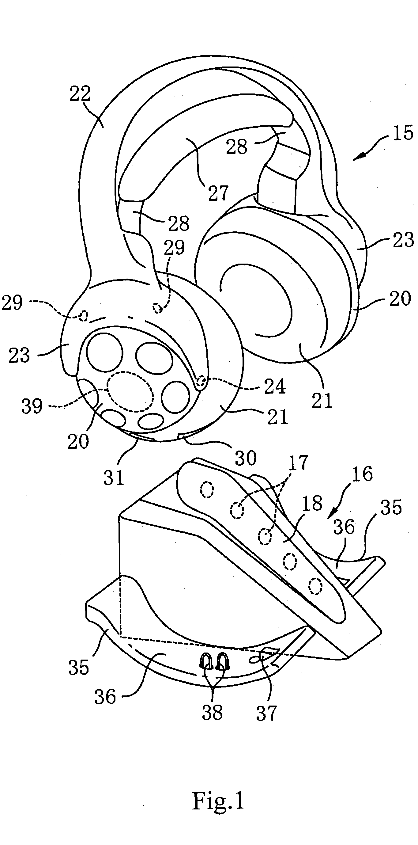
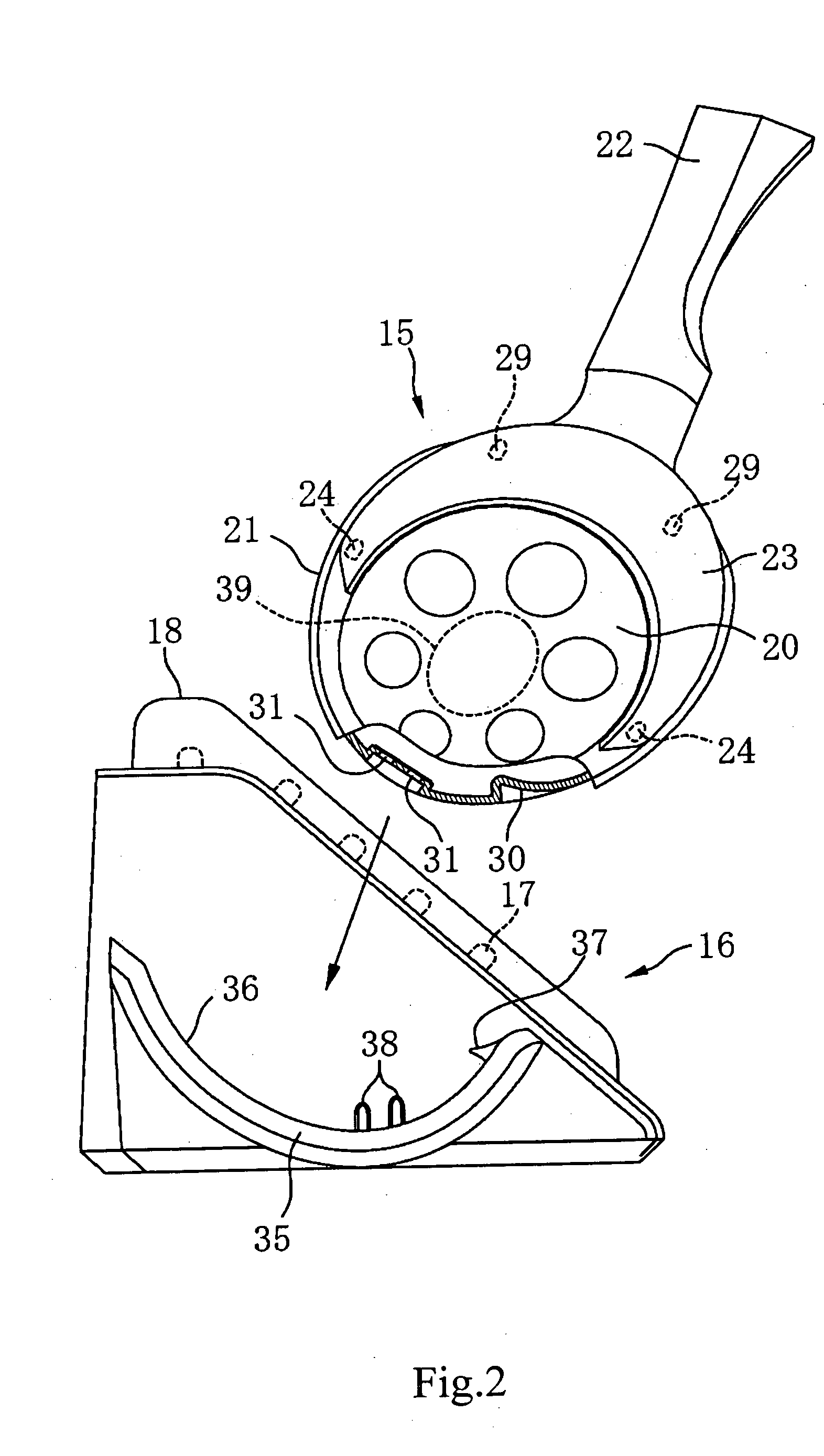
[0028] The following is a description of preferred embodiments of the present invention incorporated in this application. FIG. 1 to FIG. 6 are views showing a wireless headphone charging device of a first embodiment of this application. First, a description is given of structural characteristics using FIG. 1 to FIG. 3.

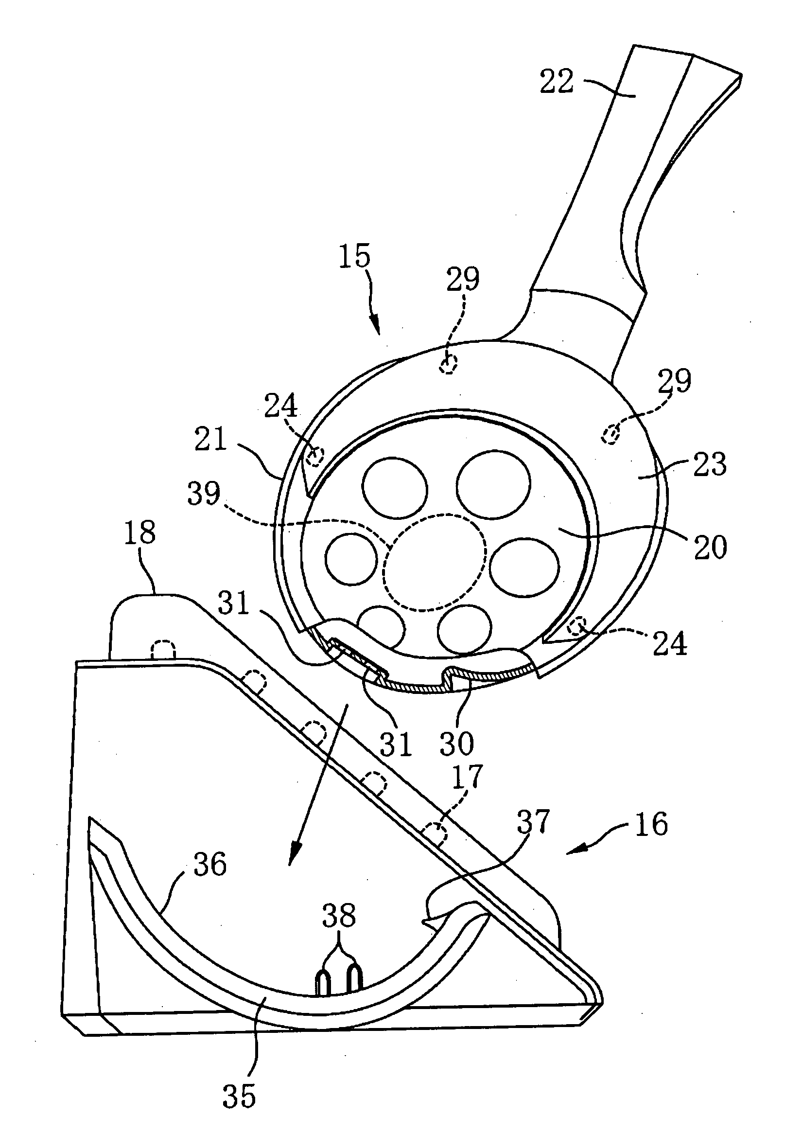
[0029] The charging device is comprised of wireless headphones 15 and a battery charger 16 for charging the headphones 15. The battery charger 16 also serves a dual purpose as the transmission means, with a plurality of infrared light-emitting elements 17 being arranged in a row at an upper portion of the front surface side at a central portion of this box. The infrared light emitting elements 17 are constructed from diodes emitting infrared rays and are covered by a cover 18.

[0030] The headphones 15 are equipped with a pair of flat, plate-shaped cases 20 constituting an output unit. The cases 20 are substantially circular or oval as viewed from the side, with pads 2...


PUM

PropertyMeasurementUnit
poweraaaaaaaaaa
forceaaaaaaaaaa
weightaaaaaaaaaa

Abstract

Charging a secondary battery (39) provided within wireless headphones (15) is carried out in a reliable manner by a charger (16) when the wireless headphones (15) are not in use. An engaged section (30) and electrodes (31) are provided at the bottom portion of a case (20) of the headphones (15). An engaging section (37) constituted by a pawl and a contact member (38) is provided on a receptacle surface (36) of a supporting plate (35) on the side of the battery charger (16). In the event that the headphones (15) are then mounted on the battery charger (16) so that the engaged section (30) is engaged by the engaging section (37) on the side of the battery charger (16), the electrodes (31) of the headphones (15) are press-attached against the contact members (38) on the side of the battery charger (16) as a result of the leverage principle.

Description

TECHNICAL FIELD [0001] The present invention relates to a charging device and charging method, and particularly relates to a charging device and charging method where an apparatus with a secondary battery built-in is mounted on a battery charger so as to charge the secondary battery. BACKGROUND ART [0002] As shown in FIG. 9, in Japanese Patent Publication No. 2770389 (patent document 1), a charging device comprising wireless headphones 1 and a transmission device 2 is disclosed. An engaging recess 3 is formed at an upper end of a cabinet of a transmission device 2. The dimensions of this engaging recess 3 are substantially the same as the width of a hanger section 4 of the headphones 1 so as to receive a protruding section 5 at a substantially central portion of the hanger section 4. [0003] When the headphones 1 are mounted on the transmission device 2 so that the protruding section 5 of the hanger section 4 inserts into the engaging recess 3, pins 6 erected at the engaging recess 3...

Claims


Application Information

Patent Timeline
Patent Type & Authority Applications(United States)
IPC IPC(8): H04R1/10H01M10/46H02J7/00H04M1/05H04M1/60H04R5/033
CPCH02J7/0044H04R5/033H04R1/1025H04R1/1008
Inventor TSUNODA, NAOTAKA
Owner SONY CORP
Why Eureka
Try Eureka