Developing device for image forming apparatus and toner container therefor

a development device and image forming technology, applied in electrographic process apparatus, instruments, optics, etc., can solve the problems of easy wear of seal members or members, easy deterioration of seal parts, so as to avoid excessive sliding movement and rapid wear of seal parts

Inactive Publication Date: 2000-10-31
RICOH KK
View PDF29 Cites 52 Cited by
  • Summary
  • Abstract
  • Description
  • Claims
  • Application Information

AI Technical Summary

Benefits of technology

It is, therefore, an object of the present invention to provide a developing device for an image forming apparatus and of the type allowing a toner container to be slid into or out of a mount portion thereof, which device can set up a sufficient contact pr

Problems solved by technology

However, when the container is slid with the edge portion of the outlet closely contacting the wall of the mount portion, a heavy load acts on the sliding movement.
Further, when the two edge portions sequentially align with each other during the sliding movement, the seal member or members wear easily due to excessive rubbing.
These load and wear problems are also apt to arise with Prior Art 5 when the container is slid into or out of the mount portion.
However, when the container is rotated with the edge portion of the outlet closely contacting the wall of the mount portion, a heavy load acts on the rotation.
Further, when the two edge portions sequentially align with each other during the rotation, the seal member or members wear easily due to excessive rubbing.
These load and wear problems are also apt to arise with Prior Art 5 when the black toner container is rotated.
The problem with Prior Art 3 is that part of the developer around the outlet of the container is apt to rush past the outlet due to the force of the rotation.
This part of the toner remains in the container until the outlet again faces downward, resulting in a low discharging efficie

Method used


Image

  • Developing device for image forming apparatus and toner container therefor
  • Developing device for image forming apparatus and toner container therefor
  • Developing device for image forming apparatus and toner container therefor

Examples


Embodiment Construction

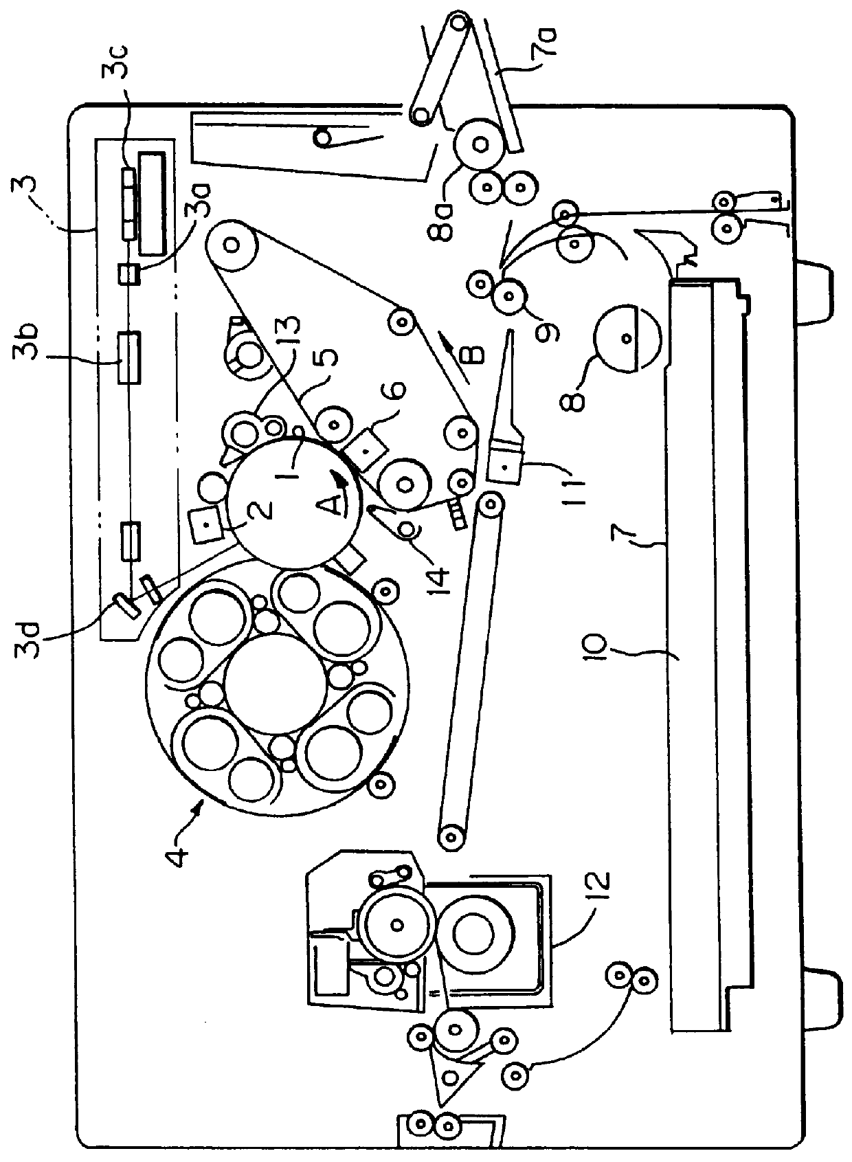
Referring to FIG. 1 of the drawings, a preferred embodiment of the present invention is shown which is applied to a color electrophotographic printer. As shown, the printer has a photoconductive drum, or image carrier, 1 which is rotated in a direction indicated by an arrow A in the figure. A main charger 2 uniformly charges the surface of the drum 1. Laser optics 3 (including optic elements 3a-3d) scan the charged surface of the drum 1 in accordance with image data and thereby electrostatically forms a latent image thereon. The image data consists of yellow data, magenta data, cyan data and black data generated by separating a desired full-color image. Latent images sequentially formed on the drum 1 are each developed by one of yellow toner, magenta toner, cyan toner and black toner stored in a rotary developing device or revolver 4 which will be described. As a result, the latent images are transformed to toner images of respective colors.

An intermediate transfer belt 5 is rotated...


PUM


Abstract

A developing device includes a toner container with a toner outlet which is formed as an opening permitting toner drop due to gravity from the toner container into a developing chamber when the opening is faced downward due to rotation of the toner container. The toner container is provided with an inner peripheral portion that is that is adjoining to the edge of the opening and protrudes toward a center line of container rotation and is on the downstream side of the opening in the direction of rotation of the toner container.

Description

BACKGROUND OF THE INVENTIONThe present invention relates to a developing device for a copier, facsimile apparatus, printer or similar image forming apparatus and, more particularly, to, in a developing device of the type having a developing chamber and a removable toner container storing toner to be replenished into the chamber, an improvement in the mounting and dismounting procedure of the container and an improvement in the replenishment of the toner from the container into a hopper.Conventional developing devices having a single developing chamber include one which allows a toner container, storing toner to be replenished into the chamber, to be slid into or out of the device body. This kind of device is taught in, for example, Japanese Utility Model Laid-Open Publication No. 2-78962 and will be referred to as Prior Art 1.Another conventional device having a single developing chamber is constructed such that a toner container is mounted to the mount portion of the device body an...

Claims


Application Information

Patent Timeline
IPC IPC(8): G03G15/01G03G15/08
CPCG03G15/0126G03G15/0868G03G15/0872G03G15/0893G03G15/0865G03G15/0855G03G2215/0116G03G2215/0177G03G2215/0665G03G2215/067G03G2215/0685G03G2215/0675
Inventor KOSUGE, KATSUHIRO
Owner RICOH KK
Why Eureka
Try Eureka