Polyaxial bone screw with shank articulation pressure insert and method

a technology of articulation pressure insert and polyaxial bone screw, which is applied in the direction of ligaments, prostheses, osteosynthesis devices, etc., can solve the problems of difficult or impossible to do, and achieve the effects of low profile, easy use and inexpensive production

Active Publication Date: 2010-08-17
JACKSON
View PDF98 Cites 193 Cited by
  • Summary
  • Abstract
  • Description
  • Claims
  • Application Information

AI Technical Summary

Problems solved by technology

This is sometimes very difficult or impossible to do.

Method used


Image

  • Polyaxial bone screw with shank articulation pressure insert and method
  • Polyaxial bone screw with shank articulation pressure insert and method
  • Polyaxial bone screw with shank articulation pressure insert and method

Examples


Embodiment Construction

[0065]As required, detailed embodiments of the present invention are disclosed herein; however, it is to be understood that the disclosed embodiments are merely exemplary of the invention, which may be embodied in various forms. Therefore, specific structural and functional details disclosed herein are not to be interpreted as limiting, but merely as a basis for the claims and as a representative basis for teaching one skilled in the art to variously employ the present invention in virtually any appropriately detailed structure.

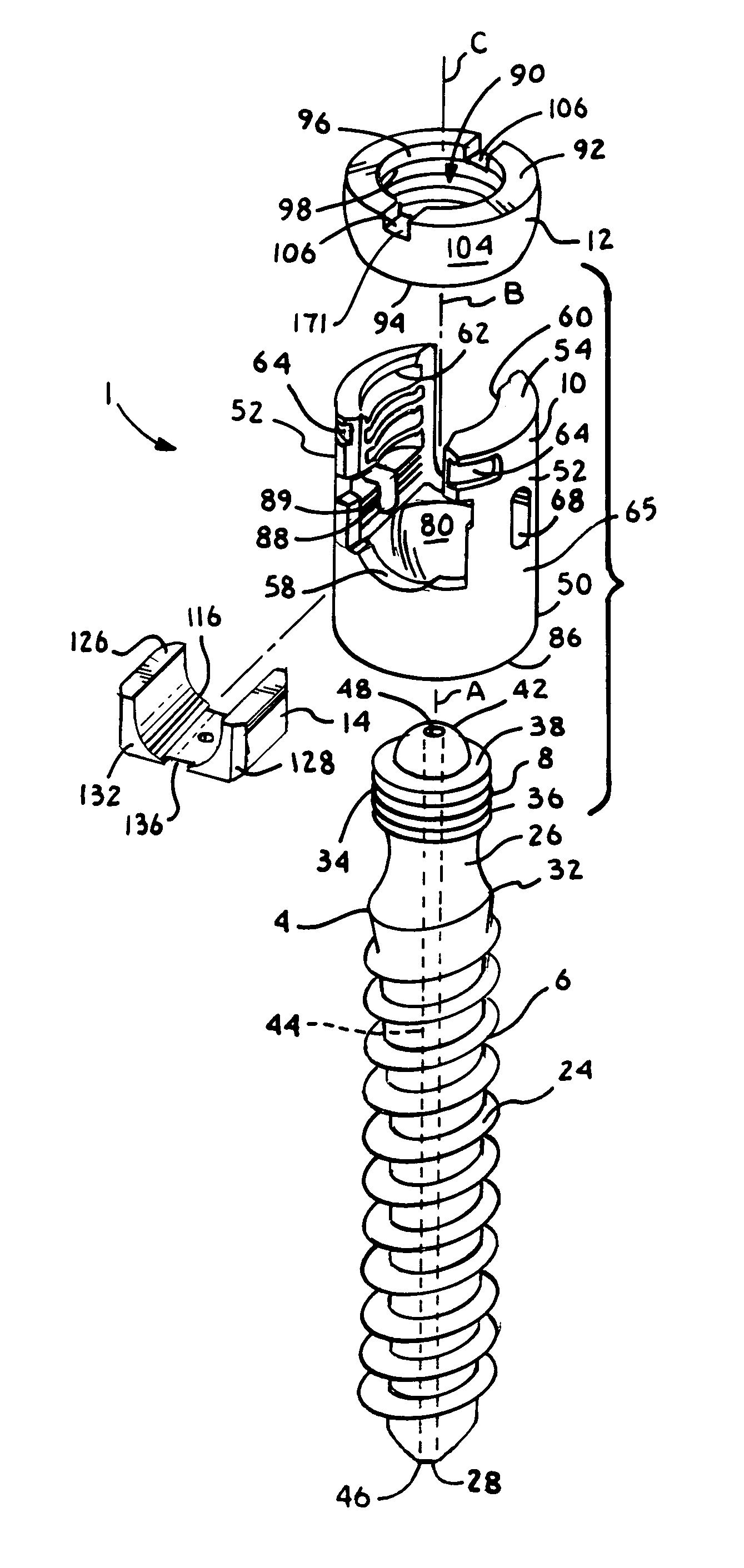
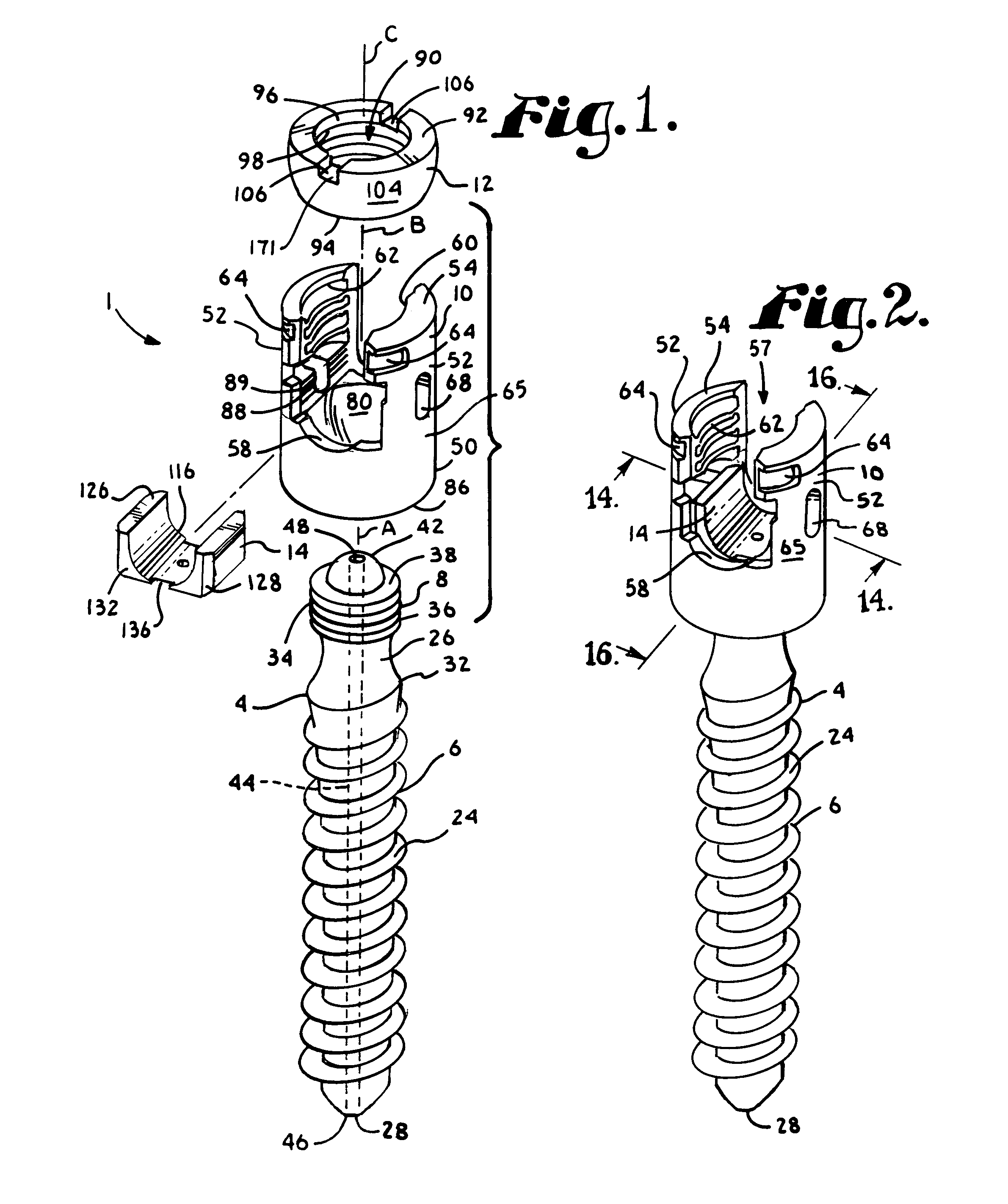
[0066]With reference to FIGS. 1-28, the reference numeral 1 generally designates a polyaxial bone screw assembly according to the present invention. The assembly 1 includes a shank 4 that further includes a body 6 integral with an upwardly extending capture structure 8; a head or receiver 10; a retaining and articulating structure or ring 12; and a side-loading pressure insert 14. The shank 4, head or receiver 10, retaining and articulating structure 12 and i...


PUM


Abstract

A polyaxial bone screw assembly includes a threaded shank body having an upper portion, a receiver member or head, a retaining and articulating structure, and a pressure insert disposed between the shank upper portion and a rod. The receiver has a U-shaped cradle defining a channel for receiving a spinal fixation rod and a receiver cavity. The retaining and articulating structure attaches to the shank and rotates with the shank in the cavity during positioning. The pressure insert presses upon the shank upper portion and not the retaining and articulating structure.

Description

BACKGROUND OF THE INVENTION[0001]The present invention is directed to polyaxial bone screws for use in bone surgery, particularly spinal surgery, and particularly to inserts for such screws.[0002]Bone screws are utilized in many types of spinal surgery, such as for osteosynthesis, in order to secure various implants to vertebrae along the spinal column for the purpose of stabilizing and / or adjusting spinal alignment. Although both closed-ended and open-ended bone screws are known, open-ended screws are particularly well suited for connections to rods and connector arms, because such rods or arms do not need to be passed through a closed bore, but rather can be laid or urged into an open channel within a receiver or head of such a screw.[0003]Typical open-ended bone screws include a threaded shank with a pair of parallel projecting branches or arms which form a yoke with a U-shaped slot or channel to receive a rod. Hooks and other types of connectors, as are used in spinal fixation t...

Claims


Application Information

Patent Timeline
Patent Type & Authority Patents(United States)
IPC IPC(8): A61B17/70
CPCA61B17/7032A61B17/7037A61B17/7082A61B17/7091A61B17/704A61B17/8605A61B2019/307A61B2090/037A61B17/7035A61B17/70F16B35/005A61B17/7001A61B17/7002
Inventor JACKSON
Owner JACKSON
Why Eureka
Try Eureka