Revolving firing pin assembly

a technology of rotating firing pins and assembly parts, which is applied in the direction of weapons, firing/trigger mechanisms, weapons, etc., can solve the problems of damage to the cannon assembly, premature firing, and injury to the user of the cannon system, and achieve the effect of improving personnel safety

Inactive Publication Date: 2010-08-24
UNITED STATES OF AMERICA THE AS REPRESENTED BY THE SEC OF THE ARMY
View PDF15 Cites 9 Cited by
  • Summary
  • Abstract
  • Description
  • Claims
  • Application Information

AI Technical Summary

Benefits of technology

[0006]The present invention satisfies this need, and presents a system and an associated method (collectively referred to herein as “the system” or “the present system”) for a revolving firing pin system for a screw-block breech of a mortar system to prevent premature firing by an electrically operated firing system.
[0008]The present system enables screw-block breech-loading mortar systems that enhance personnel safety. The screw-block breech-loading mortar system utilizing the present system may be transported while loaded with ammunition without the ammunition being accidentally fired. The mortar ammunition can only be fired when the screw-block breech is rotated and locked in position.

Problems solved by technology

This actuation may permit the firing pin to strike the primer and can lead to premature firing.
Premature firing can result in damage to the cannon assembly and injury to the cannon system user; i.e., a soldier.
Modifying ammunition for use of conventional mortar ammunition in a breech-loaded system is both costly and time-consuming.
The need for such a system has heretofore remained unsatisfied.

Method used


Image

  • Revolving firing pin assembly
  • Revolving firing pin assembly
  • Revolving firing pin assembly

Examples


Embodiment Construction

[0015]The following definitions and explanations provide background information pertaining to the technical field of the present invention, and are intended to facilitate the understanding of the present invention without limiting its scope:

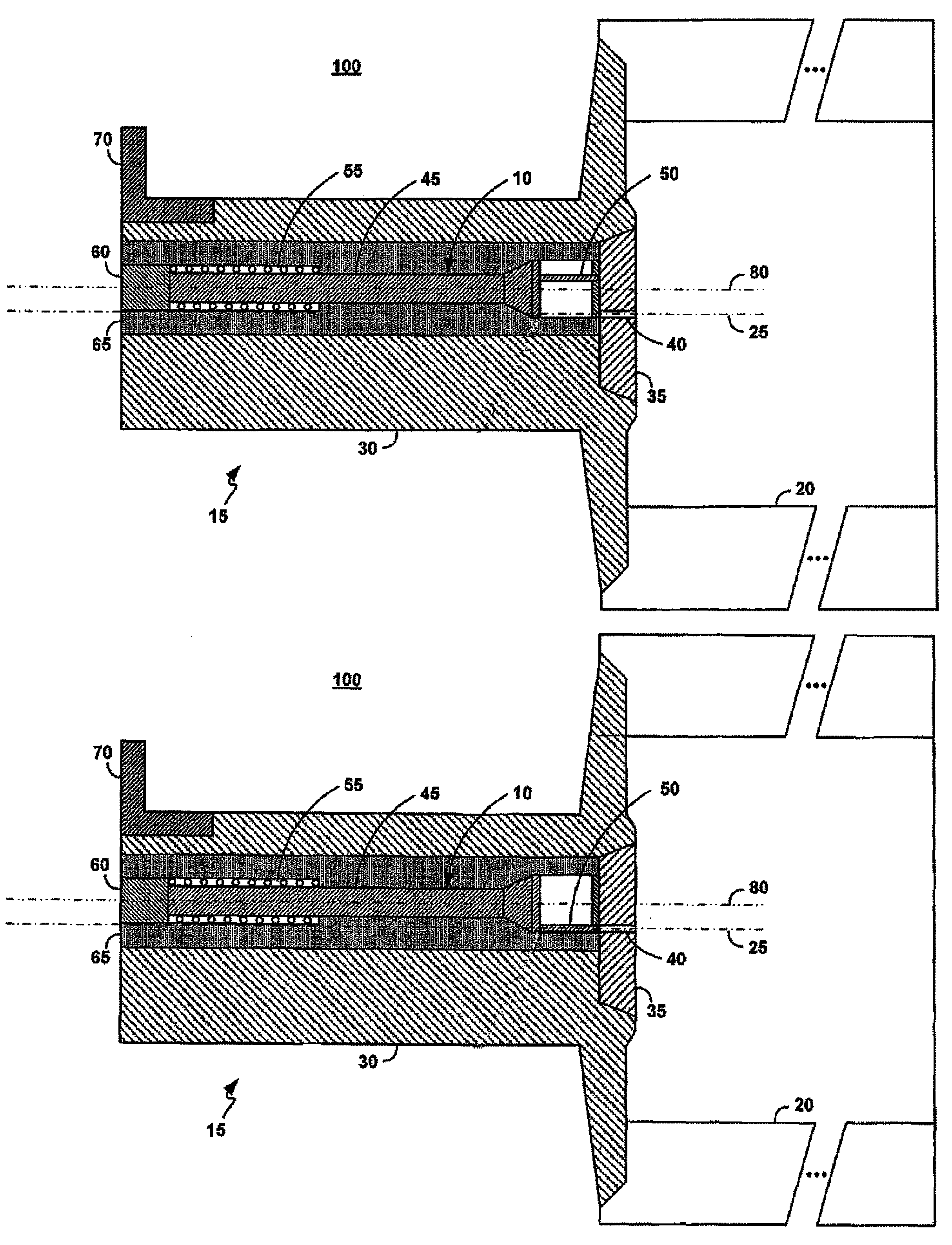
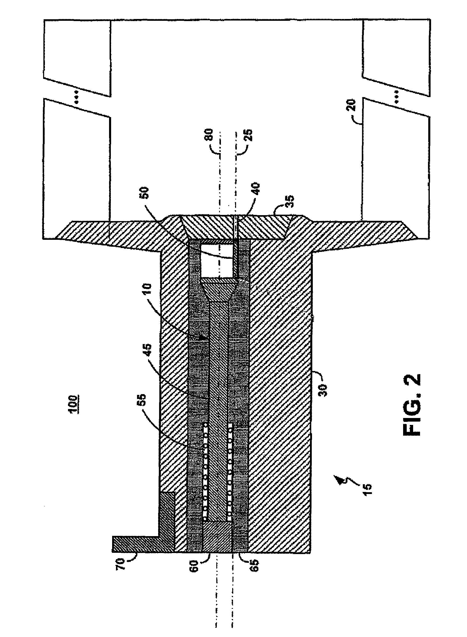
[0016]FIG. 1 illustrates an exemplary high-level cross-section diagram of a screw-block breech-loading weapon system 100 (interchangeably referenced herein as the mortar system 100 or the weapon system 100) comprising a revolving firing pin system 10 (interchangeably referenced herein as system or screw block assembly) that is mounted onto a canon (or weapon 20) at a proximal end, and a solenoid 45 at a distal end.

[0017]The screw block assembly 15 comprises a spindle 30 and a spindle cap 35. The spindle cap 35 comprises a firing pin hole 40 that is offset relative to a center axis of the firing pin system. The spindle 30 houses a revolver firing pin assembly 65 that rotates around a spindle axis 25. The revolver firing pin assembly 65 comprises a...


PUM


Abstract

A revolving firing pin system is mechanically linked to a screw-block in a breech-loading mortar system, wherein the revolver firing pin assembly rotates on a centerline that is offset from the centerline of the screw-block assembly. When the revolver firing pin assembly is rotated, the firing pin assembly also rotates. However, until the screw-block assembly is locked, the firing pin is in a safety position that is not in line with the primer of the munition loaded into the mortar system. Only when the screw-block is rotated into a locked position does the firing pin align with the primer of the munition to thus be able to strike the primer when the solenoid is electronically actuated.

Description

U.S. GOVERNMENT INTEREST[0001]The inventions described herein may be manufactured, used and licensed by or for the U.S. Government for U.S. Government purposes.FIELD OF THE INVENTION[0002]The present invention generally relates to a screw block assembly for a breech-loaded weapon, the screw-block assembly comprising a firing pin for a weapon such as having a cannon, or such as in a 120 MM breech loaded Mortar weapon. In particular, the present invention relates to aligning of a firing pin in a safety position when the screw-block breech is not closed and locked.BACKGROUND OF THE INVENTION[0003]In comparison to muzzle-loaded weapons, breech-loaded weapons are advantageous in that ammunition is loaded through the breech of the weapon rather than the muzzle of the weapon. Consequently, breech-loaded weapons allow faster operation and improve personnel safety. Modern breech-loaded mortar weapons typically rely on modifications to ammunition or use heavy slide-block breeches. Although th...

Claims


Application Information

Patent Timeline
Patent Type & Authority Patents(United States)
IPC IPC(8): F41A19/27
CPCF41A17/66F41A19/13F41A19/27F41F1/06
Inventor HOLMES, EDWARDBENNETT, LEEFORKAS, DONALDHATHAWAY, IV, GEORGE
Owner UNITED STATES OF AMERICA THE AS REPRESENTED BY THE SEC OF THE ARMY
Why Eureka
Try Eureka