Hinged pocket

a pocket and hinge technology, applied in the field of pocket, can solve the problems of added cost, difficult to retrieve magazines, and easy to be accidentally dislodged and lost, and achieve the effect of being convenient and reliabl

Active Publication Date: 2010-08-24
HERE BE DRAGONS LLC
View PDF24 Cites 38 Cited by
  • Summary
  • Abstract
  • Description
  • Claims
  • Application Information

AI Technical Summary

Benefits of technology

[0009]The present invention overcomes the problems associated with prior art pockets, and does so in an inexpensive and reliable manner. In accordance with the present invention, a pocket comprises an inner cup cooperating in a nested relationship with an outer cup to define a chamber having a closed bottom end and an open upper end sized to receive an ammunition magazine or other like flat sided article. Hinge assemblies interconnect the inner and outer cups at the closed bottom end of the chamber. The hinge assemblies are configured to accommodate swinging movement of the outer cup relative to the inner cup between a closed position at which the flat sides of the article received in the chamber are tightly confined between opposite interior surfaces of the inner and outer cups, and a release position deflected outwardly from the closed position to accommodate removal of the article from the chamber via its open end. The outer cup is yieldably urged into its closed position by a resilient closure.

Problems solved by technology

However, the exposed magazines are thus prone to being accidentally dislodged and lost as the soldiers maneuver vigorously during combat operations.
Moreover, once the shielding flaps of the fully enclosed pockets are tucked out of the way, magazine retrieval remains problematical.
These loops, however, add additional cost, require additional effort to configure, and still require that the magazines be gripped during extraction in a manner that is suboptimal for rapid insertion into the weapons.
Thus, secure retention is unavoidably accompanied by disadvantageously high insertion and extraction forces.

Method used


Image

  • Hinged pocket
  • Hinged pocket
  • Hinged pocket

Examples


Embodiment Construction

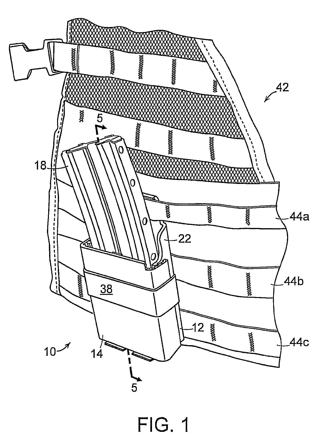
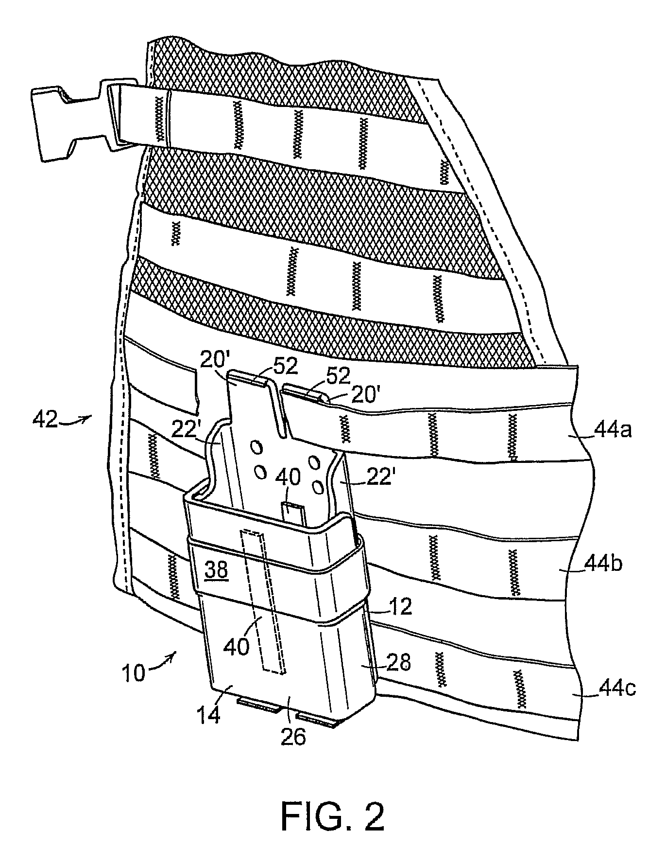
[0019]With reference initially to FIGS. 1-6, a hinged pocket in accordance with the present invention is generally depicted at 10. The pocket includes an inner cup 12 cooperating in a nested relationship with an outer cup 14 to define a chamber 16 having a closed bottom end and an open upper end sized to receive an article, e.g., an ammunition magazine 18.

[0020]The inner cup 12 has a back wall 20, parallel first side walls 22 and a first bottom wall 24 extending between the first side walls 22. The outer cup 14 has a front wall 26, parallel second side walls 28 and a second bottom wall 30 extending between the second side walls 28. The second bottom wall 30 extends beneath the first bottom wall 24, with the first side walls 22 confined between the second side walls 28.

[0021]The back wall 20 is subdivided at its upper end into stabilizing tabs 20′, and the first side walls 22 define upper guiding surfaces 22′. The stabilizing tabs 20′ and guiding surfaces 22′ project vertically above...


PUM


Abstract

A pocket comprises an inner cup cooperating in a nested relationship with an outer cup to define a chamber having a closed bottom end and an open upper end sized to receive an article. A hinge interconnects the inner and outer cups at the closed bottom end of the chamber. The hinge is configured to accommodate swinging movement of the outer cup relative to the inner cup between a closed position at which the sides of the article received in the chamber are tightly confined between opposite interior surfaces of the inner and outer cups, and a release position deflected outwardly from the closed position to accommodate removal of the article from the chamber via its open upper end.

Description

BACKGROUND DISCUSSION[0001]1. Field of the Invention[0002]This invention related generally to pockets for flat-sided articles such as ammunition magazines, PDA's, telephones, radios, and the like, and is concerned in particular with an improved hinged pocket designed to accommodate rapid insertion, secure retention, and rapid retrieval of such articles.[0003]2. Description of the Prior Art[0004]In the military field, conventional magazine pockets are either fully closed by shielding flaps that serve to protect the magazines from exposure to dirt, dust, and other contaminants, or are partially closed by straps serving primarily to prevent the magazines from falling out, or are left open with interior cushioned surfaces serving to retain the magazines in place.[0005]When using fully or partially enclosed pockets in dangerous areas, soldiers will usually open the tops of spare pockets by tucking their shielding flats or straps behind the magazines to facilitate easier access under dure...

Claims


Application Information

Patent Timeline
Patent Type & Authority Patents(United States)
IPC IPC(8): A45F5/00
CPCA41D13/0012F41C33/02F42B39/02F42B39/26Y10S224/931
Inventor HOWELL, FRANK A.
Owner HERE BE DRAGONS LLC
Why Eureka
Try Eureka