Failure tolerant passive lubrication system

a passive lubrication and failure-tolerant technology, applied in the direction of turbines, machines/engines, mechanical equipment, etc., to achieve the effect of low cost, reliable, and substantial maintenance fr

Active Publication Date: 2007-02-13
RTX CORP
View PDF28 Cites 34 Cited by
  • Summary
  • Abstract
  • Description
  • Claims
  • Application Information

AI Technical Summary

Benefits of technology

[0009]The principal advantage of the invention is that it operates passively, i.e. without relying on sensors, valves, control systems or actuators to detect the malfunction and engage the auxiliary circuit. As a result, the system is inexpensive, reliable and substantially maintenance free. Another advantage, especially for aircraft applications, is that the system is light weight and compact. The compactness of the invention allows it to be located deep in the interior of the engine where its vulnerability to battle damage is minimized.
is that it operates passively, i.e. without relying on sensors, valves, control systems or actuators to detect the malfunction and engage the auxiliary circuit. As a result, the system is inexpensive, reliable and substantially maintenance free. Another advantage, especially for aircraft applications, is that the system is light weight and compact. The compactness of the invention allows it to be located deep in the interior of the engine where its vulnerability to battle damage is minimized.

Problems solved by technology

During abnormal conditions, such as after a malfunction that degrades or disables the engine's main lubrication circuit, the auxiliary circuit continues to operate until the lubricant in the reservoir is depleted.

Method used


Image

  • Failure tolerant passive lubrication system
  • Failure tolerant passive lubrication system
  • Failure tolerant passive lubrication system

Examples


Embodiment Construction

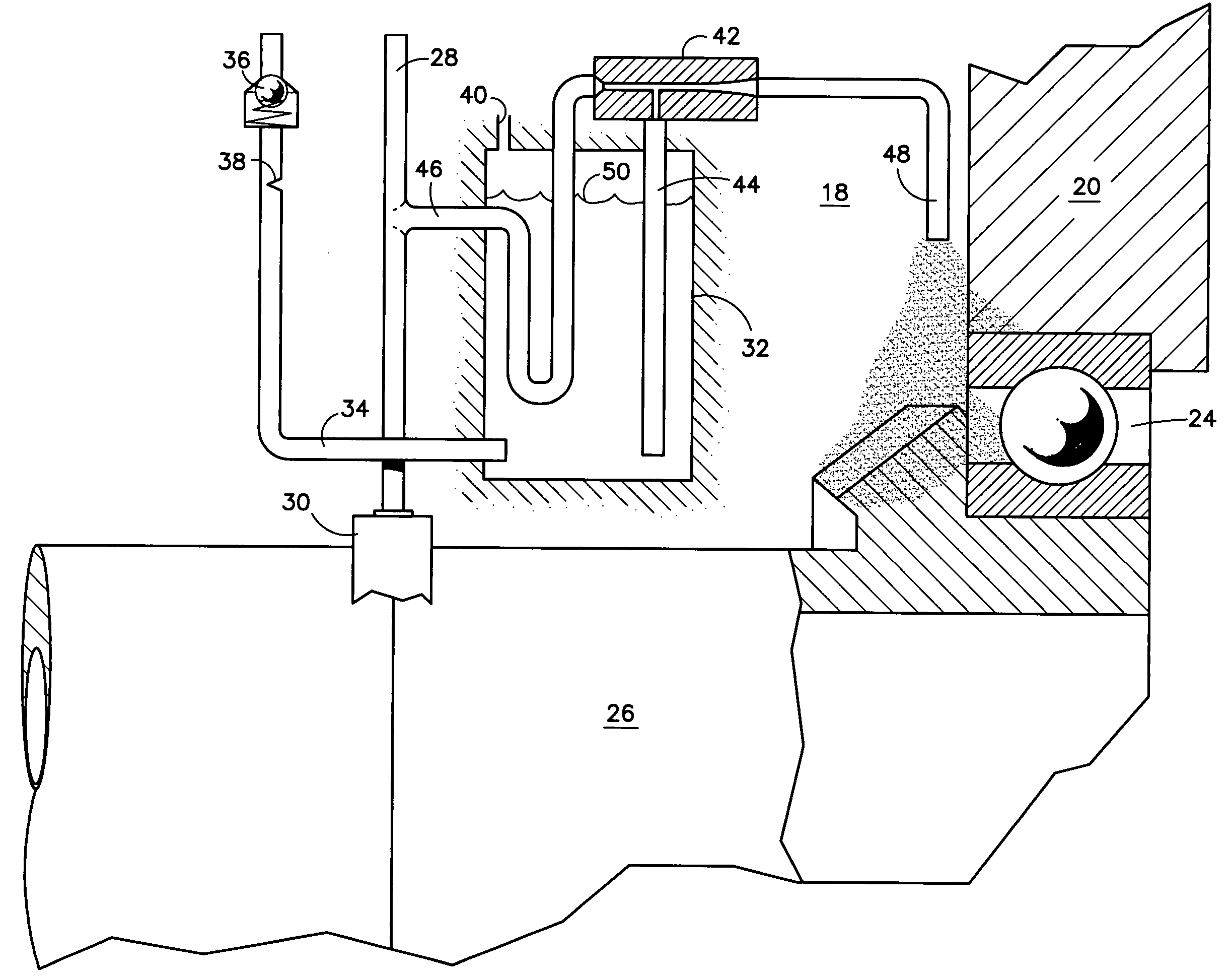
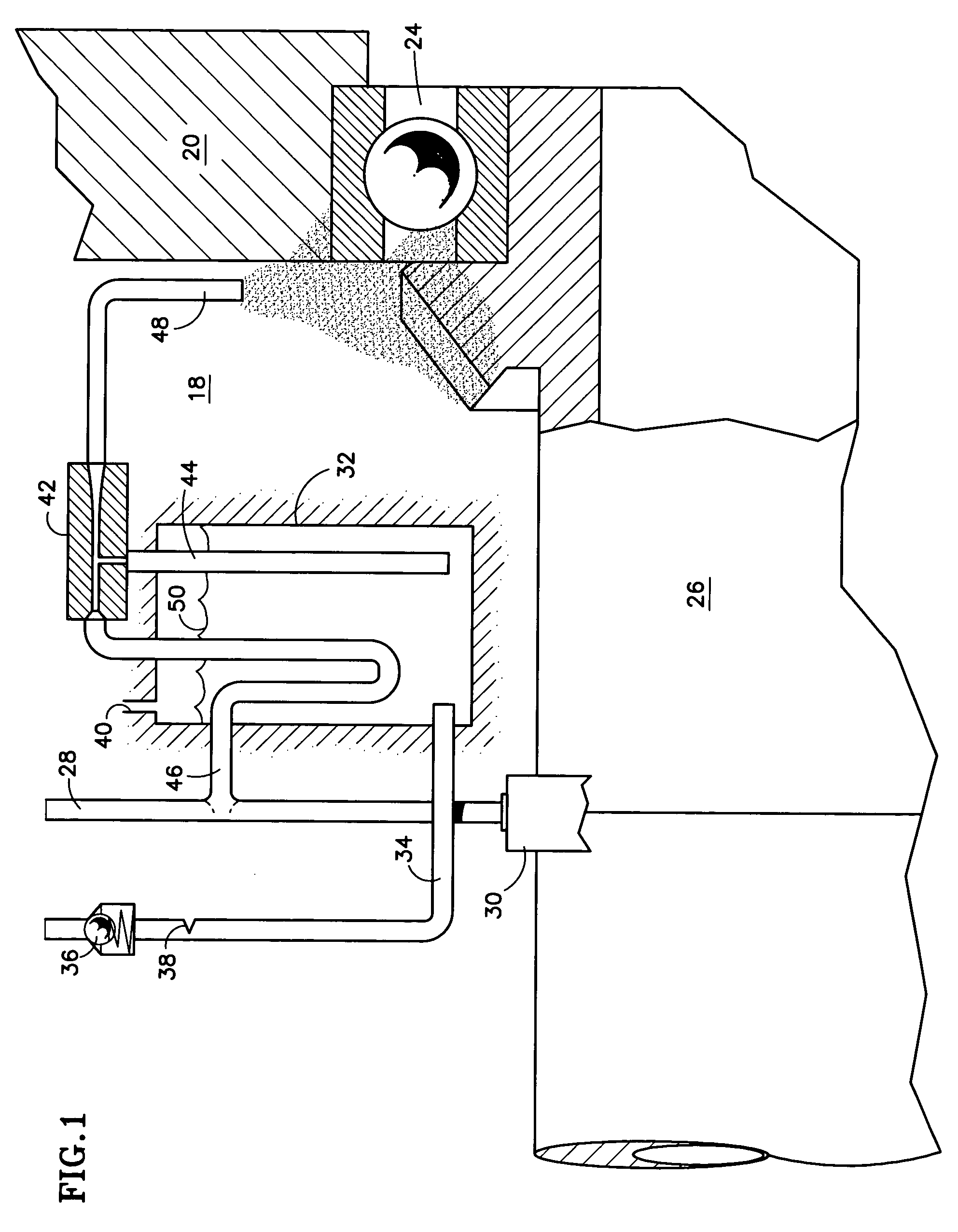
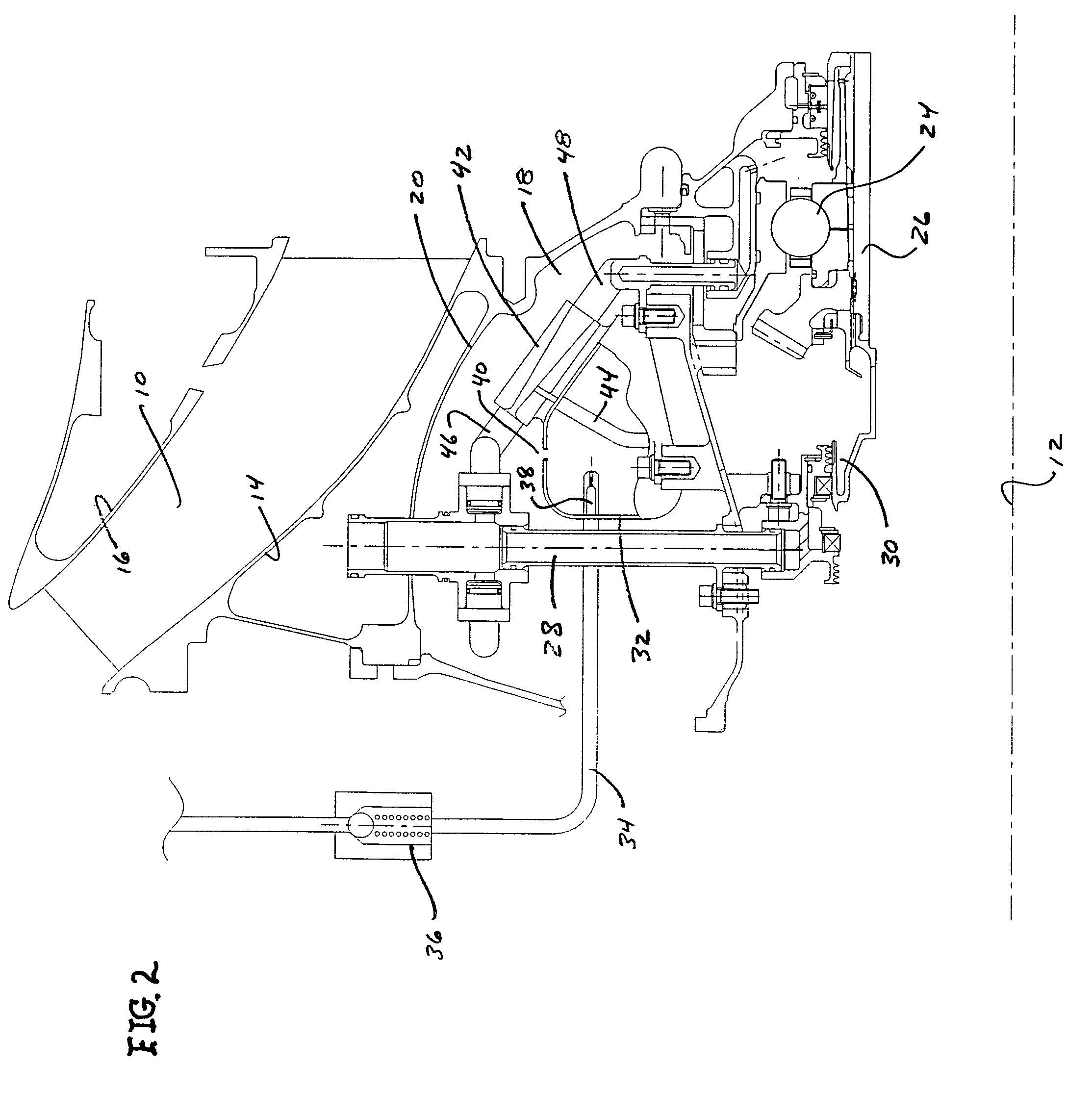
[0012]Referring to FIGS. 1 and 2, a gas turbine engine includes an annular flowpath 10 circumscribing an axially extending centerline or axis 12. Radially inner and outer case walls 14, 16 define radially inner and outer boundaries of the flowpath. A bearing compartment 18 defined by enclosure 20 resides radially inboard of the flowpath. A bearing 24 resides within the compartment and supports an engine rotor or shaft 26. The illustrated portion of the flowpath is a duct extending between low pressure and high pressure compressors, neither of which is illustrated. The duct carries a pressurized working medium fluid, specifically compressed air, from the low pressure compressor to the high pressure compressor.

[0013]A buffer air supply tube 28 extends radially inwardly from just inboard of case wall 14 to a location proximate a seal 30 at the front of the bearing compartment. During engine operation, a small amount of compressed air from the flowpath enters the supply tube 28 by way o...


PUM


Abstract

An auxiliary lubrication system for an aircraft turbine engine includes a reservoir 32 of lubricant 50 and a venturi 42 to suction lubricant out of the reservoir and direct an lubricant mist at a bearing 24 or other component requiring lubrication. The venturi is directly connected to a source of motive fluid, such as pressurized air extracted from an engine flowpath 10, and is continuously driven by the motive fluid. The auxiliary system accommodates a failure or malfunction of the primary, high pressure lubrication system. The auxiliary system operates during normal conditions, when the primary system is fully functional. If the primary system fails, the auxiliary system continues to operate for a limited time, until the lubricant in the reservoir is depleted, to provide an lubricant mist to the component being lubricated. The limited-duration lubricant supply allows the aircraft crew time to carry out actions required to safeguard the aircraft and its occupants.

Description

STATEMENT OF GOVERNMENT INTEREST[0001]This invention was made under U.S. Government Contract N00019-02-C-3003. The Government has certain rights in the invention.TECHNICAL FIELD[0002]This invention relates to lubrication systems and particularly to a lubrication system capable of supplying lubricant for a limited time following a failure or malfunction of a system component.BACKGROUND OF THE INVENTION[0003]Lubrication systems, such as those used in aircraft gas turbine engines, supply lubricant to bearings, gears and other engine components that require lubrication. The lubricant, typically oil, cools the components and protects them from wear. A typical oil lubrication system includes conventional components such as an oil tank, pump, filter and oil supply conduits.[0004]If one of the lubrication system components fails, malfunctions or sustains damage, the oil supply to the lubricated component may be disrupted resulting in irreparable damage to the component and undesirable corol...

Claims


Application Information

Patent Timeline
Patent Type & Authority Patents(United States)
IPC IPC(8): F01M1/00F01D25/18F02C7/06F16N7/32F16N29/00
CPCF01D25/16F01D25/18F16C33/6662F16N7/32F16N29/00Y02T50/671F16N2210/02F16N2260/20F16N2260/50F16C19/52F16C2360/23Y02T50/60
Inventor SHERIDAN, WILLIAM G.
Owner RTX CORP
Why Eureka
Try Eureka