

Molded lead frame connector with one or more passive components
a technology of passive components and connectors, which is applied in the direction of coupling device connections, semiconductor/solid-state device details, instruments, etc., can solve the problems of increasing the cost of flex circuits, reducing the reliability of flex circuits, and increasing the overall cost of transceiver modules, etc., to achieve reliable and inexpensive effects
- Summary
- Abstract
- Description
- Claims
- Application Information
AI Technical Summary
Benefits of technology
Problems solved by technology
Method used
Image

Examples
Embodiment Construction
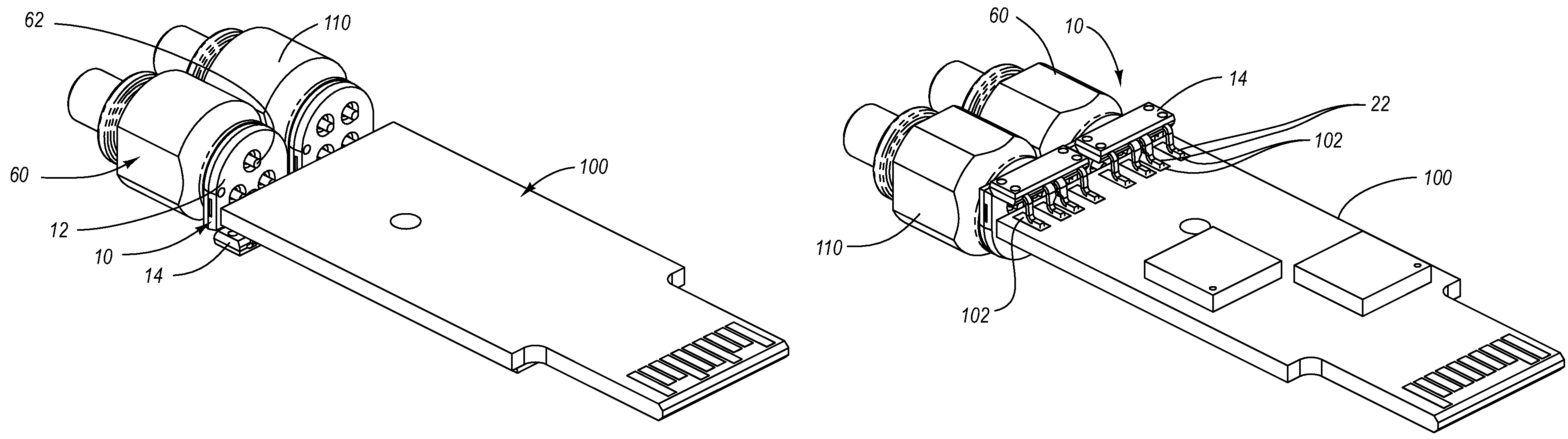
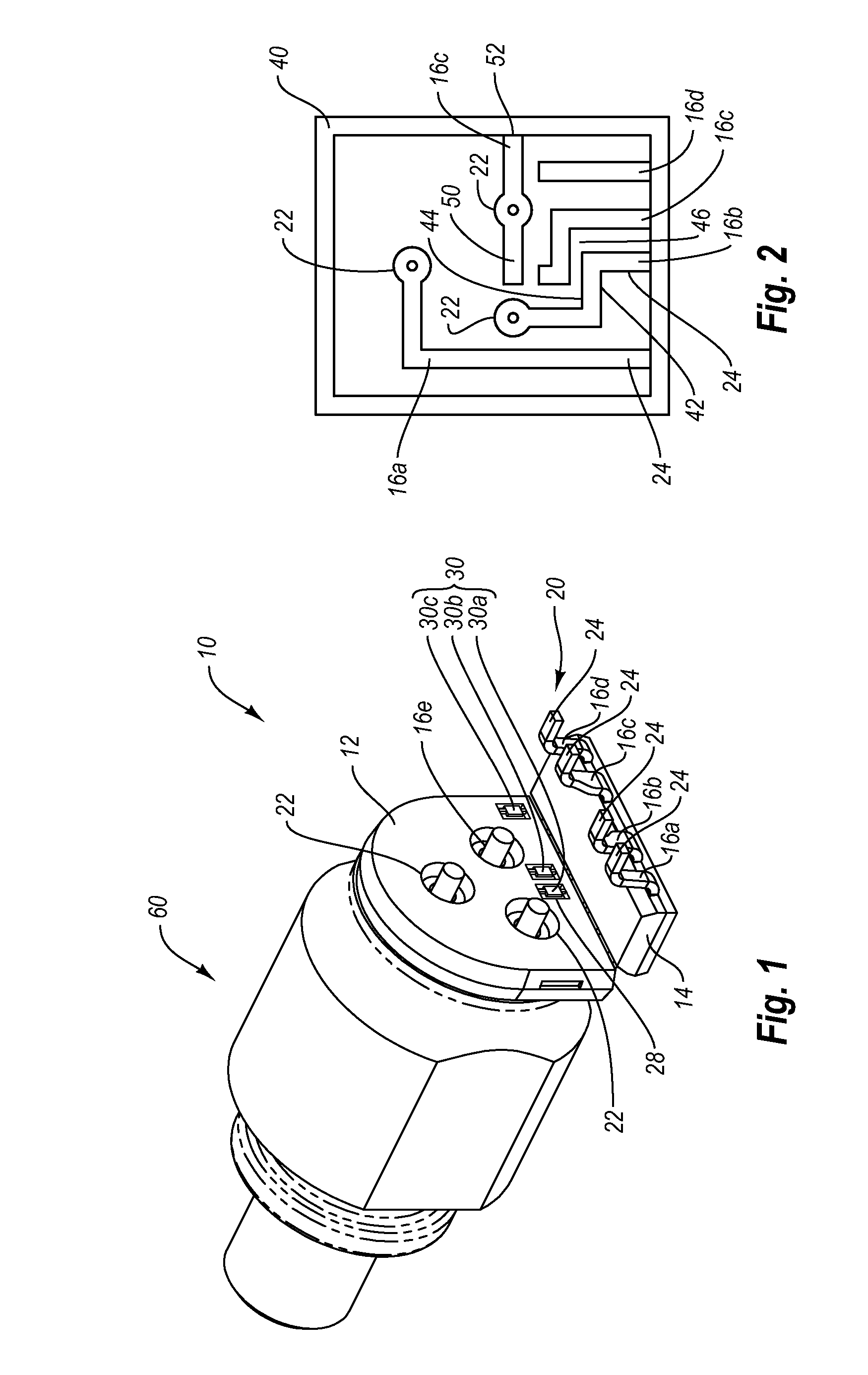
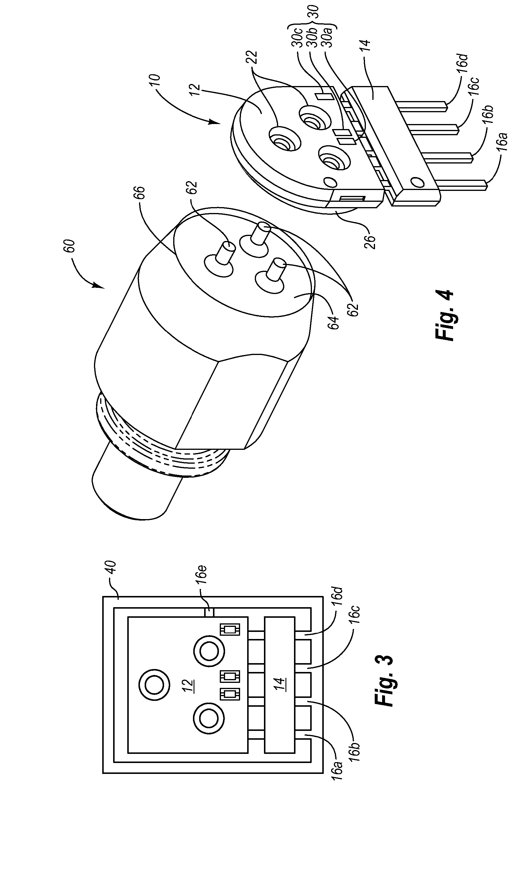
[0012]Embodiments of the present invention relate to lead frame connectors that are used to electrically and mechanically connect optical sub-assemblies (OSAs) to printed circuit boards in optical transceiver modules. The lead frame connectors enable optical sub-assemblies to be connected to the printed circuit board in optical transceiver modules in a reliable and inexpensive manner, while maintaining desired radio frequency (RF) responses of the modules. The use of such lead frame connectors eliminates the need for flexible printed circuit boards that have been used in conventional transceiver modules. The lead frame connector eliminates the problems associated with signal reflection caused by unmatched impedances with the connection between the OSA and the printed circuit board.
[0013]According to one embodiment, the lead frame connector includes a conductive structure that can be encased within a casing. The casing provides electrical insulation for the conductors in the lead fra...
PUM
 Abstract
Description
Claims
Application Information