Parallel-tuned pick-up system with multiple voltage outputs

a pickup system and voltage output technology, applied in the direction of ac-dc conversion, inductance, power electronics conversion, etc., can solve the problems of 2 not being able to produce an additional independent output voltage, voltage transformer connected across the rectifier,

Inactive Publication Date: 2010-08-24
AUCKLAND UNISERVICES LTD
View PDF49 Cites 71 Cited by
  • Summary
  • Abstract
  • Description
  • Claims
  • Application Information

AI Technical Summary

Benefits of technology

[0008]It is an object of the present invention to provide an ICPT system with a parallel tuned pick-up that is capable of producing two or more independently controlled output voltages which reduces or overcomes one or more of the abovementioned limitations, or which will at least provide the public with a useful alternative.

Problems solved by technology

However, the input voltage to the rectifier bridge B 302 falls to nearly zero on very light loads corresponding to very low power transfer, so that a voltage transformer connected across the rectifier bridge as shown in FIG. 2 cannot be used to produce an additional independent output voltage.
Such devices are expensive, and are not generally available for voltages at the top end of this range.
Another disadvantage with using the first output is that the high voltage needs to be maintained even when the load it supplies is in an “off” state.

Method used


Image

  • Parallel-tuned pick-up system with multiple voltage outputs
  • Parallel-tuned pick-up system with multiple voltage outputs
  • Parallel-tuned pick-up system with multiple voltage outputs

Examples


Embodiment Construction

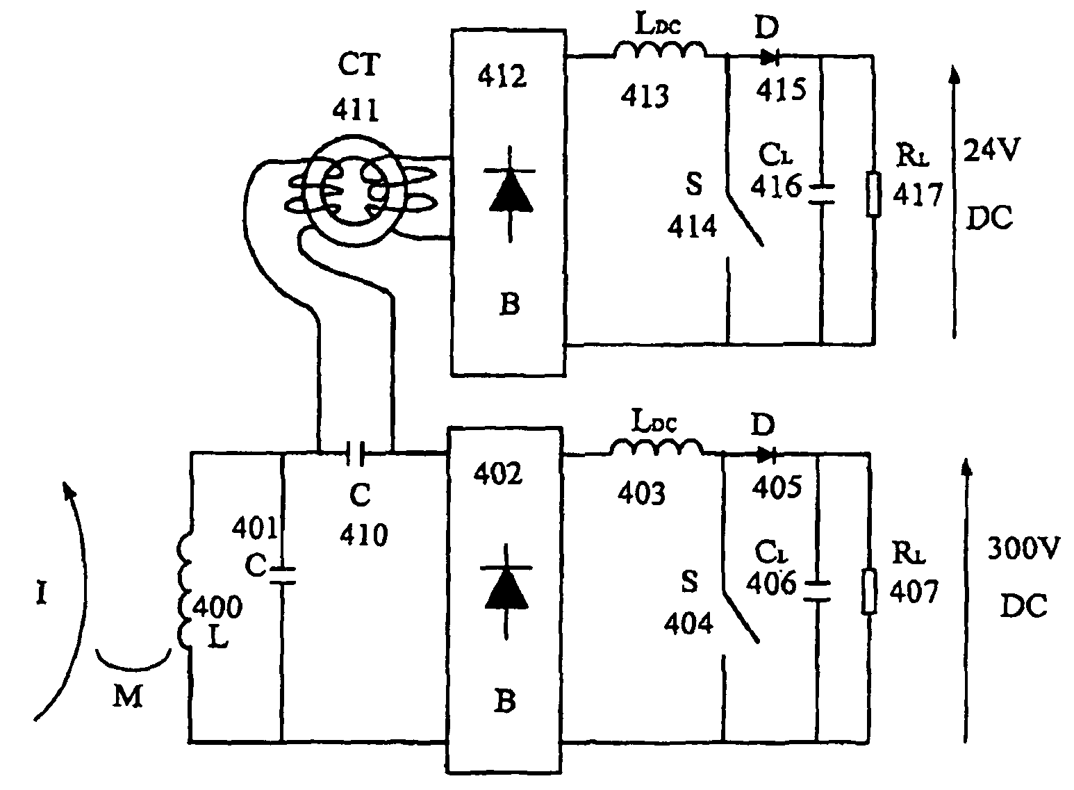
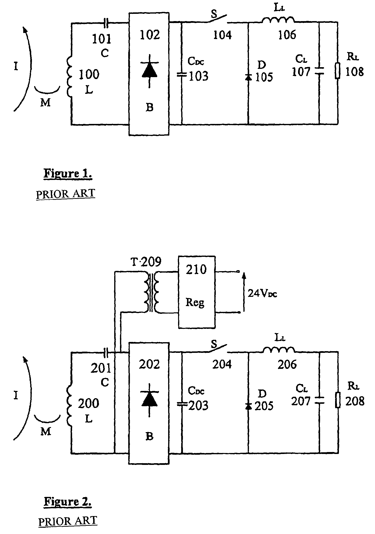
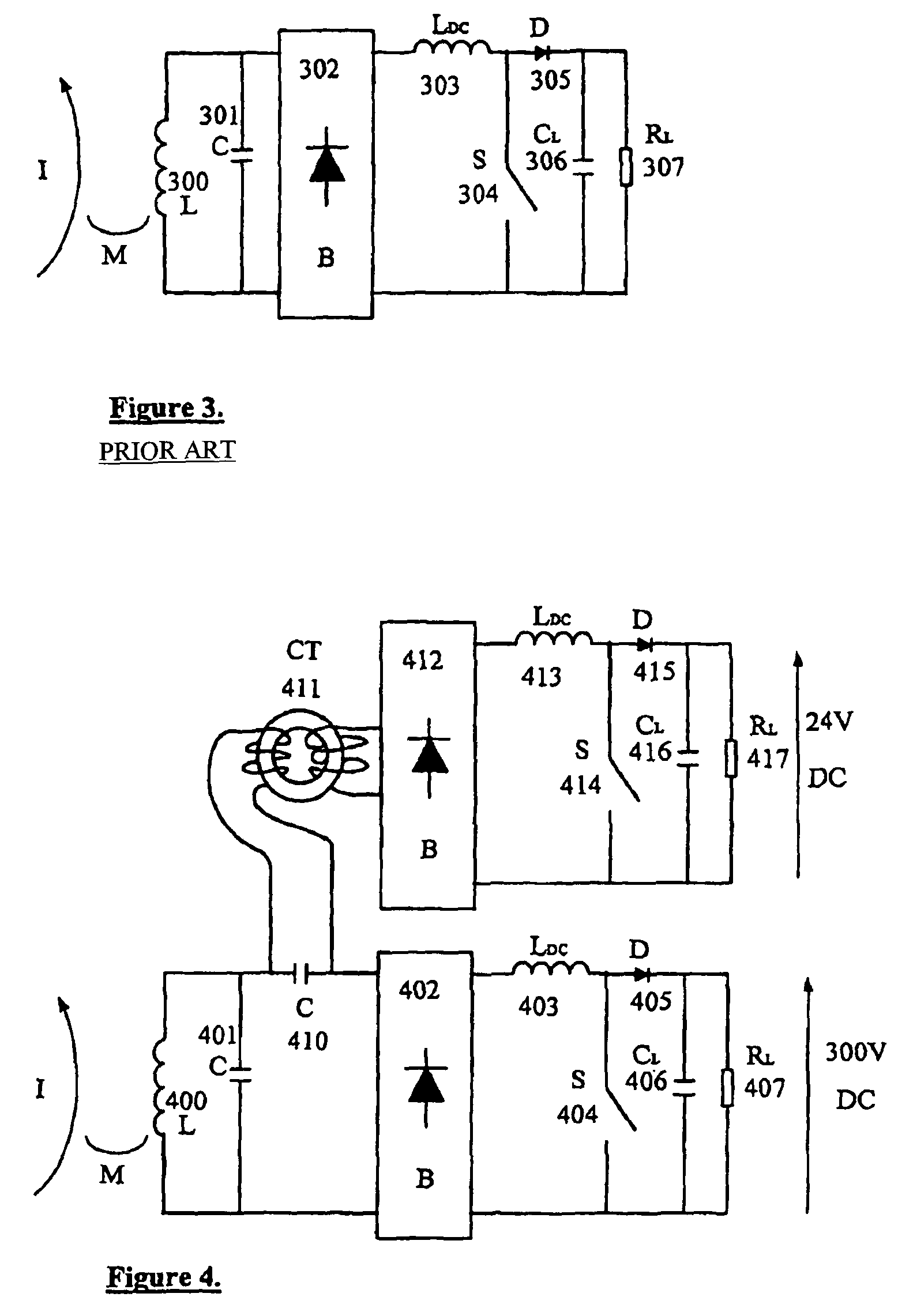
[0046]FIG. 4 shows a circuit of the invention with two independently controllable outputs. With the parallel tuned circuit of FIG. 3 L 300 and C 301 (also shown in FIG. 4 as L 400 and C 401) the AC input current to the rectifier bridge B 302 (B 402) is essentially constant, with a magnitude given by

[0047]I⁢⁢ML,

and is independent of either the load resistor 307 (first load 407) or the state of the switch S 304 (the switch S 404 of the first control circuit). Thus, adding current transformer CT 411, shown in FIG. 4, in series with the pick-up resonant circuit allows a transformed constant (AC) current to be input to rectifier bridge B 412 of the additional control circuit.

[0048]The circuitry of the additional control circuit after rectifier bridge B 412 (413 to 417) is identical in concept to that of FIG. 3 (303 to 307; and to the circuitry of components 403 to 407 of the first control circuit in FIG. 4) allowing a completely independent output voltage—eg 24 V DC—to be produced. Switc...


PUM

PropertyMeasurementUnit
output voltageaaaaaaaaaa
voltageaaaaaaaaaa

Abstract

A pick-up is provided for an Inductively Coupled Power Transfer (ICPT) system having a parallel tuned resonant pick-up circuit. The pick-up has a plurality of independently controllable power supply outputs. This allows a first output to supply a high voltage load (e.g. 300V-550V) and one or more additional outputs for supplying other loads such as control circuitry which may only require 24V. The one or more additional outputs may be supplied via a current transformer connected in series with the resonant pick-up circuit. Control for each output may be achieved by partially or completely decoupling the pick-up from a primary conductive path of the ICPT system.

Description

CROSS REFERENCE TO PRIOR APPLICATION[0001]This is a U.S. National Phase application under 35 U.S.C. §371 of International Patent Application No. PCT / NZ2004 / 000102, filed May 26, 2004, which claims priority to New Zealand Patent Application No. 526109, filed on May 26, 2003. The International Application was published on Dec. 2, 2004 as WO 2004 / 105207 A1 under PCT Article 21(2).FIELD OF THE INVENTION[0002]This invention relates to Inductively Coupled Power Transfer (ICPT) systems, particularly parallel tuned pick-ups for ICPT systems.BACKGROUND TO INVENTION[0003]ICPT systems generally consist of two electrically isolated parts. The first is a trackway or primary conductive pathway which is usually supplied with a very low frequency (VLF; typically 5-50 kHz) current. The primary conductive pathway is usually elongate but can take a variety of different forms.[0004]The second part, which is usually referred to as a pick-up, supplies an electrical load with power derived from the primar...

Claims


Application Information

Patent Timeline
Patent Type & Authority Patents(United States)
IPC IPC(8): H01F27/42H02J5/00H02M7/217
CPCH02J5/005H02M7/217H02M2001/009Y02B70/1441Y02B70/10H02J50/12H02M1/009
Inventor BOYS, JOHN T.
Owner AUCKLAND UNISERVICES LTD
Why Eureka
Try Eureka