RFID tag disabling systems and methods of use

a technology of rfid transponder and tag, which is applied in the direction of burglar alarm mechanical actuation, burglar alarm by hand-portable object removal, instruments, etc., can solve the problems of inability to temporarily disable rfid transponder permanently attached to the vehicle, tag has to be removed from the windshield, and the technique is not suitable for temporary disassembly and installation of rfid transponder

Active Publication Date: 2010-08-24
AMTECH SYST
View PDF9 Cites 36 Cited by
  • Summary
  • Abstract
  • Description
  • Claims
  • Application Information

AI Technical Summary

Problems solved by technology

If a person was alone and wanted to drive in the HOT / HOV lane, they too would be allowed, but would have to pay tolls, and therefore would not be allowed to use the tag disabling device.
The disadvantage of this type of tag disabling method is that the tag has to be removed from the windshield to accomplish it.
While the foregoing techniques for temporarily disabling or shielding RFID transponders are generally suitable for their intended purposes for their specific applications, such techniques are not suitable for temporarily disabling RFID transponders that are permanently affixed to a vehicle, e.g., sticker tags bearing RFID transponders secured to the inner surface of the vehicle's windshield or RFID transponders encapsulated in the windshield itself.
A disadvantage of the permanently mounted ‘sticker’ tags, however, is that they can't be temporarily disabled.
For example, once removed from the windshield, the adhesive on a windshield sticker tag, such as that produced by Transcore, Inc., can be damaged.
Since the antenna design in this tag relies on uniform close proximity to the glass for proper operation, the tag cannot be reused.
RFID tags can be permanently disabled by mechanical destruction of the conductive patterns on the tag.
While permanent tag disabling has certain viable applications, by definition it is unsuitable for applications where the tag is to be disabled only temporarily and so that it can be reused at some later time.

Method used


Image

  • RFID tag disabling systems and methods of use
  • RFID tag disabling systems and methods of use
  • RFID tag disabling systems and methods of use

Examples


Embodiment Construction

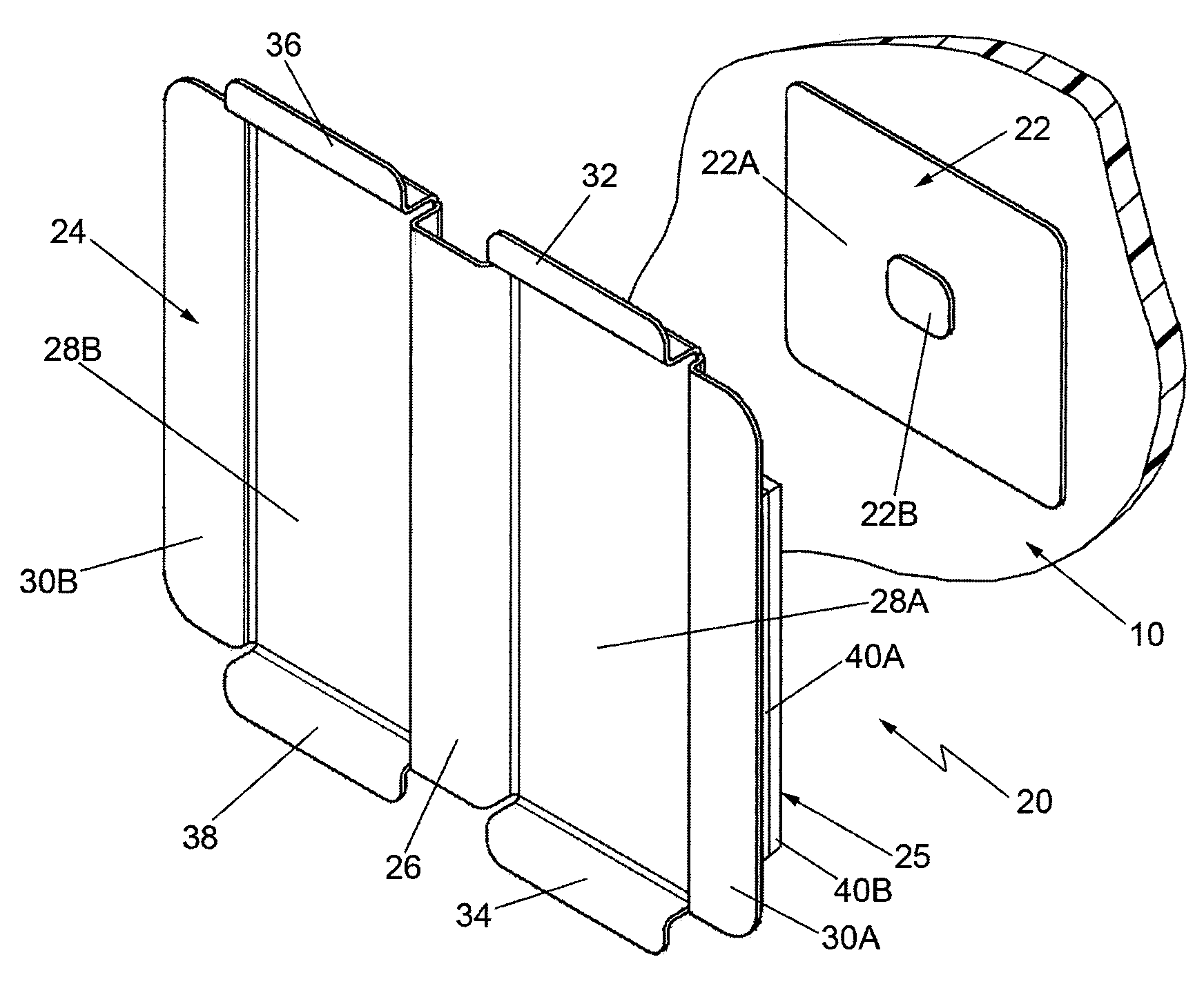
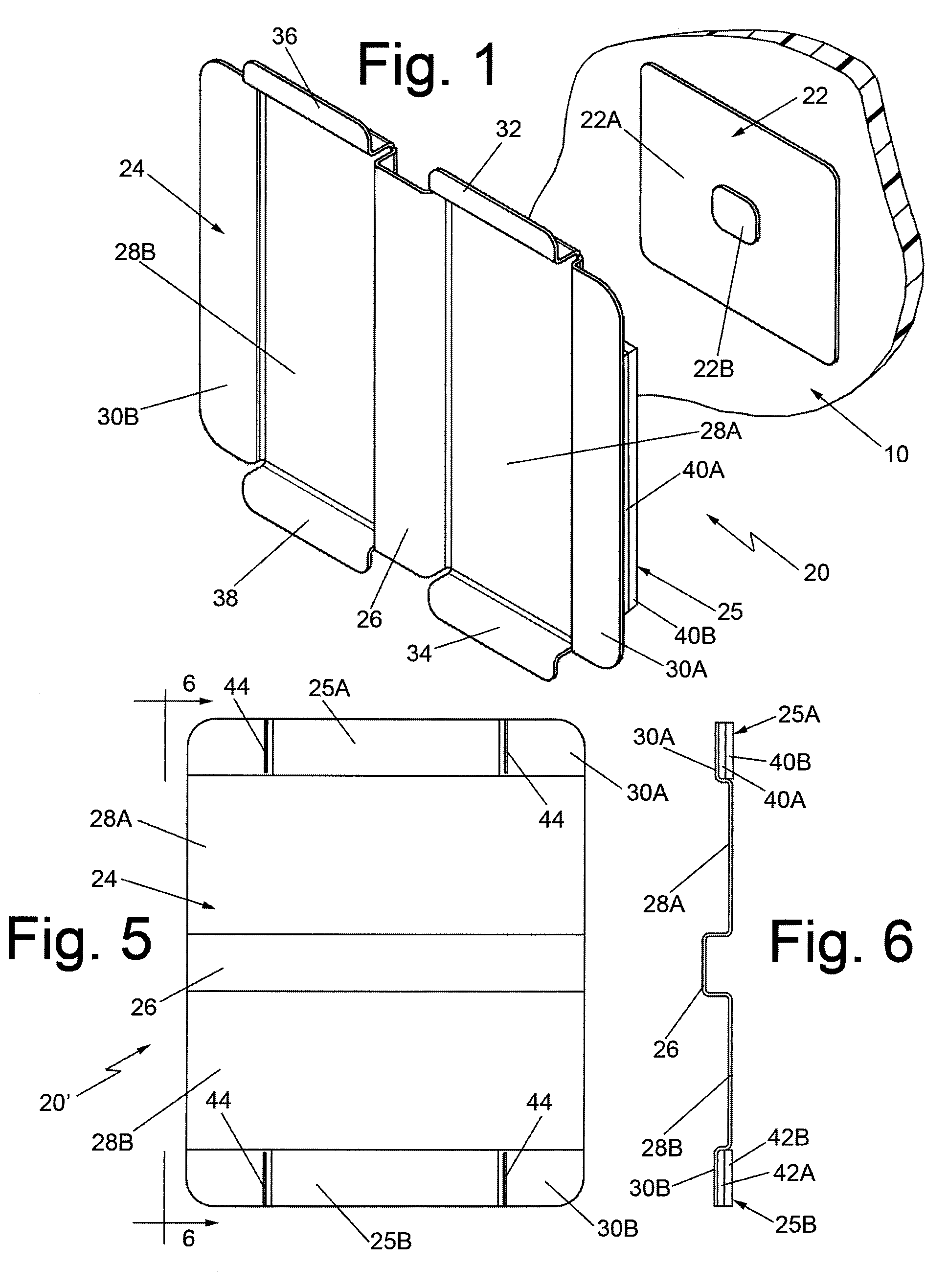
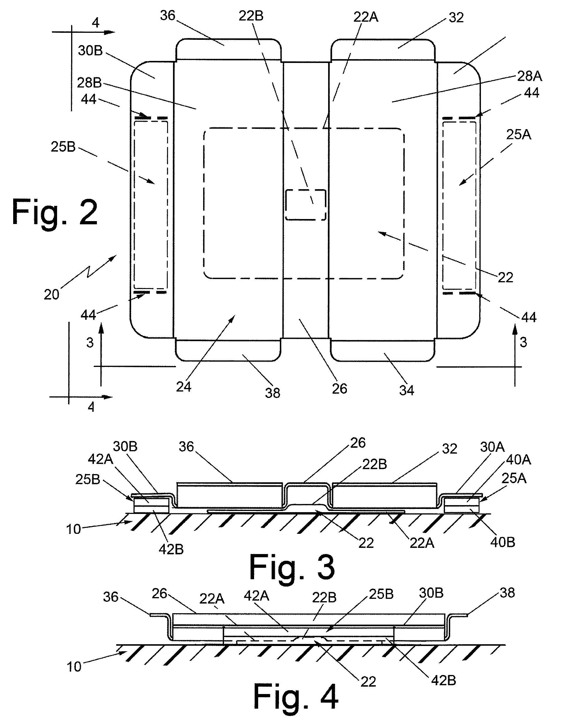
[0026]Referring now to the drawing wherein like characters refer to like parts, there is shown in FIGS. 1 and 5, exemplary tag disabling devices 20 and 20′, respectively, each of which is arranged for selectively disabling an RFID transponder 22 used in an electronic toll system (not shown), an electronic parking system or any other system, such as vehicular access control, traffic monitoring, parking, and the like wherein a vehicle with the RFID tag is to be interrogated by a reader to determine the vehicle's presence at a certain location. The tag disabling devices 20 and 20′ are exemplary of a multitude of tag disabling devices that can be constructed in accordance with this invention. Such tag disabling devices have particular utility for use with RFID tags that are permanently or fixedly secured to the vehicles to selectively disable such tags, yet permit their ready re-enablement. Examples of transponders fixedly secured to the windshield of a vehicle with which the tag disabl...


PUM


Abstract

Systems and methods for disabling transponders used in electronic toll collection or other RFID systems, wherein the transponders include an antenna and RFID circuitry. The transponders can be selectively disabled by releasably securing a disabling device having a metallic portion at an operative position over the antenna of the RFID system, whereupon the metallic portion is coupled to the antenna in such a manner as to disable the RFID circuitry so long as the disabling device is at the operative position. The RFID circuitry is arranged to be automatically enabled upon removal of the disabling device from the operative position.

Description

CROSS-REFERENCE TO RELATED APPLICATIONS[0001]“Not Applicable”STATEMENT REGARDING FEDERALLY SPONSORED RESEARCH OR DEVELOPMENT[0002]“Not Applicable”INCORPORATION-BY-REFERENCE OF MATERIAL SUBMITTED ON A COMPACT DISK[0003]“Not Applicable”BACKGROUND OF THE INVENTION[0004]This invention relates generally to RFID transponder systems and more particularly for disabling devices and methods of use for selectively disabling RFID transponders when desired.[0005]In response to the inability of conventional toll collection means to meet the demands created by increased highway traffic, automated toll facilities that provide improved toll collection methods and systems have been proposed and are being implemented. These electronic toll collection systems eliminate the manual transactions of conventional toll collection means through the use of radio transmitters and receivers that perform the necessary transactions as a vehicle travels through the automated toll booth. For example, U.S. Pat. No. 7...

Claims


Application Information

Patent Timeline
Patent Type & Authority Patents(United States)
IPC IPC(8): G08B13/14
CPCG06K19/07327
Inventor BURNETT, MATTHEW K.NOAKES, SCOTTMESTAS, FRANK
Owner AMTECH SYST
Why Eureka
Try Eureka