Hole digging device

a technology for digging devices and soils, applied in manure treatment, agriculture, agricultural tools and machines, etc., can solve the problems of time-consuming and particularly strenuous digging holes in soils or other materials

Active Publication Date: 2010-08-31
WRIGHT DON I
View PDF12 Cites 11 Cited by
  • Summary
  • Abstract
  • Description
  • Claims
  • Application Information

AI Technical Summary

Problems solved by technology

Digging holes in soil or other materials can be particularly strenuous and time consuming.

Method used


Image

  • Hole digging device
  • Hole digging device
  • Hole digging device

Examples


Embodiment Construction

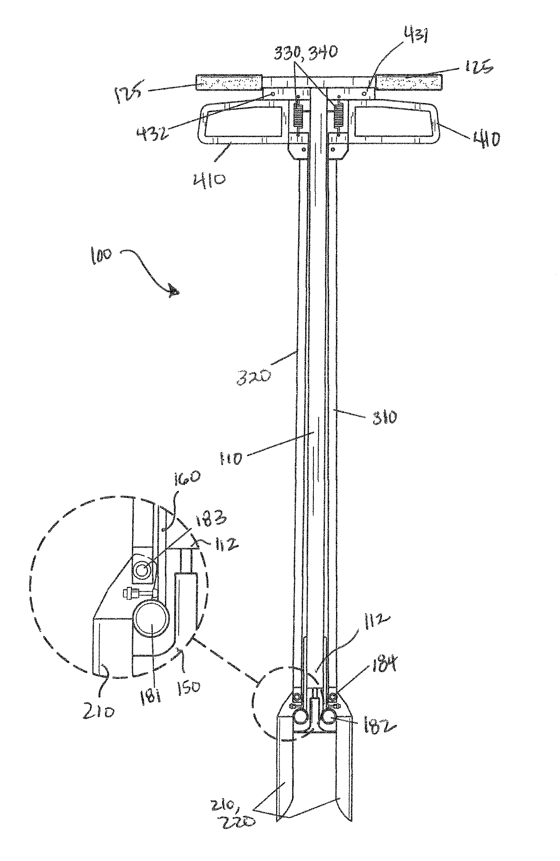
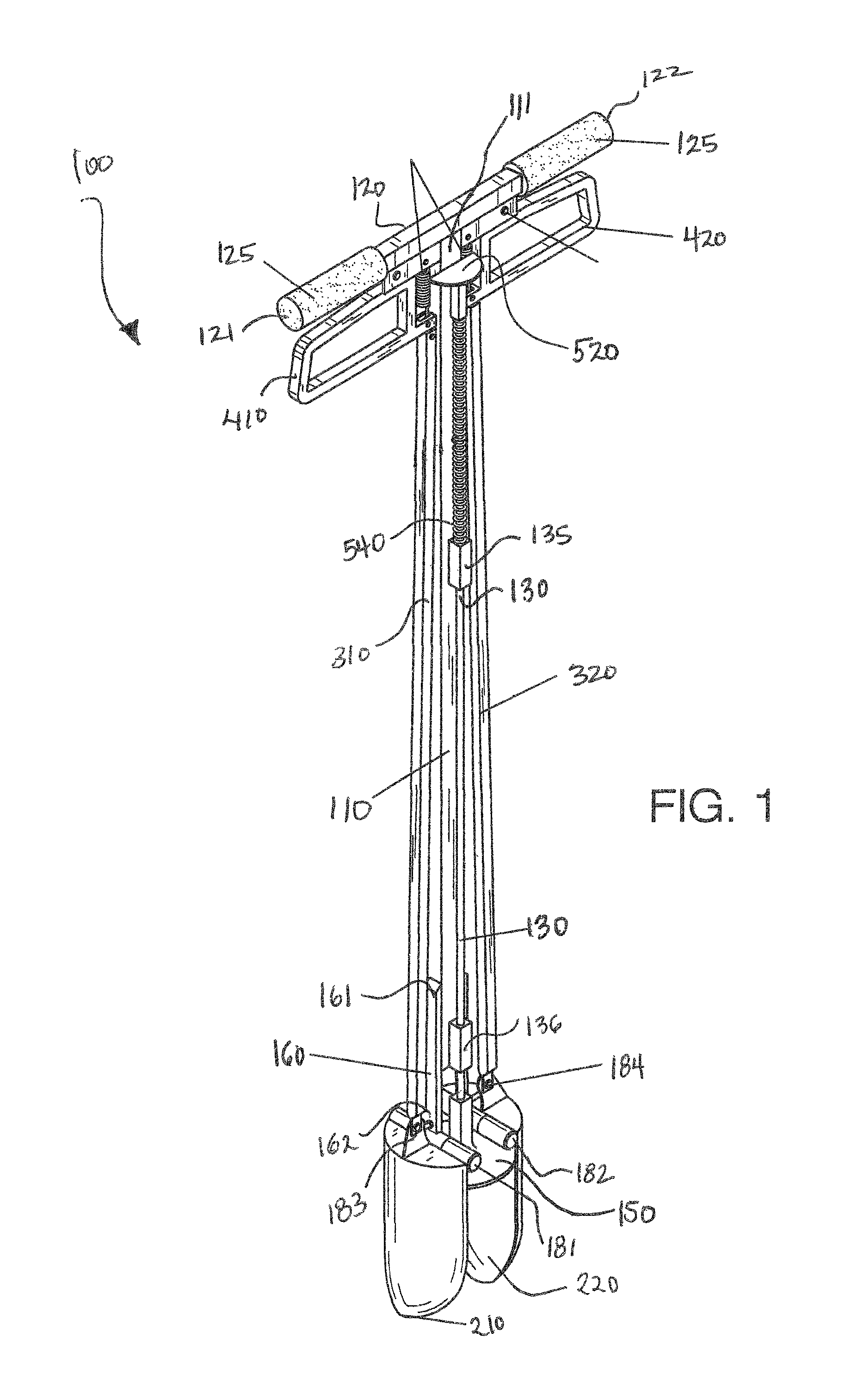
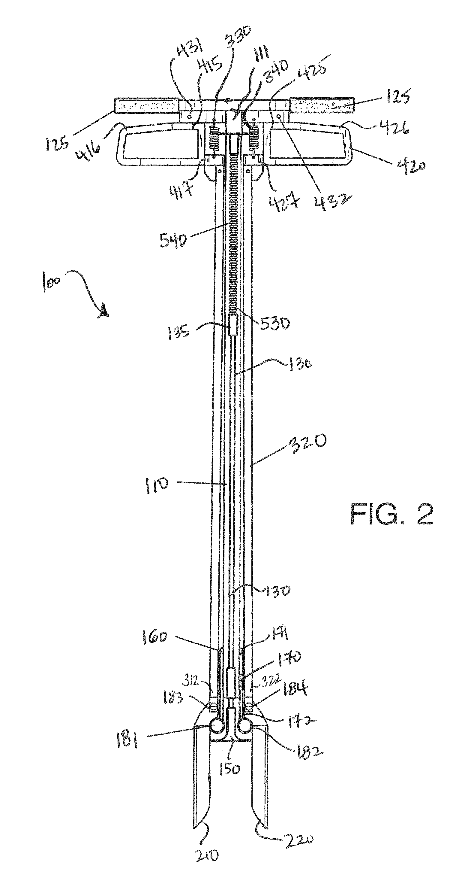
[0009]The following is a listing of numbers corresponding to a particular element refer to herein:[0010]100 hole digging device[0011]110 central shaft[0012]111 first end of central shaft[0013]112 second end of central shaft[0014]120 crossbar[0015]121 first side end of crossbar[0016]122 second side end of crossbar[0017]130 push rod[0018]135 first rod guide[0019]136 second rod guide[0020]150 base[0021]160 first support brace[0022]161 first end of first support brace[0023]162 second end of first support brace[0024]170 second support brace[0025]171 first end of second support brace[0026]172 second end of second support brace[0027]181 first hinge[0028]182 second hinge[0029]183 third hinge[0030]184 fourth hinge[0031]210 first digging blade[0032]220 second digging blade[0033]310 first digging blade shaft[0034]311 first end of first digging blade shaft[0035]312 second end of first digging blade shaft[0036]320 second digging blade shaft[0037]321 first end of second digging blade shaft[0038]3...


PUM


Abstract

A hole digging device comprising a shaft having a crossbar perpendicularly attached; a push rod parallel to the shaft; a circular base on the second end of the push rod and a handle on the first end of the push rod, wherein the handle, push rod, and base can altogether move between an up position and a down position; two braces attached to the shaft on opposing sides; two digging blades pivotally attached to the braces, wherein the digging blades can pivot between an engaged position or a disengaged position; two blade shafts parallel to the central shaft, wherein the digging blades are pivotally attached to the blade shafts; two grasping loops pivotally attached to the crossbar opposite each other and moveable between an up position and a down position; wherein the grasping loops are biased in the down position caused by springs.

Description

FIELD OF THE INVENTION[0001]The present invention is directed to a device for digging holes in soil or other materials, more particularly to a digging device comprising digging blades that can be pivoted inwardly to help remove soil from a particular region of the ground.BACKGROUND OF THE INVENTION[0002]Digging holes in soil or other materials can be particularly strenuous and time consuming. The present invention features a hole digging device. The digging device of the present invention comprises blades that can be pivoted inwardly to provide an easier means of removing soil from the ground. The device can help a user dig a hole more easily and more efficiently.[0003]Any feature or combination of features described herein are included within the scope of the present invention provided that the features included in any such combination are not mutually inconsistent as will be apparent from the context, this specification, and the knowledge of one of ordinary skill in the art. Addit...

Claims


Application Information

Patent Timeline
Patent Type & Authority Patents(United States)
IPC IPC(8): A01B1/02
CPCA01C5/02
Inventor WRIGHT, DON I.
Owner WRIGHT DON I
Why Eureka
Try Eureka