[0009]Preferably, the valve arrangement can also be opened by a pressure from the steering unit. With this embodiment it is ensured that the steering unit can also always act upon the steering motor, when the feedback suppression device is active. Thus, the steering unit has a higher priority than the feedback suppression device, so that the feedback suppression device does not have to be disconnected or deactivated to enable a steering.
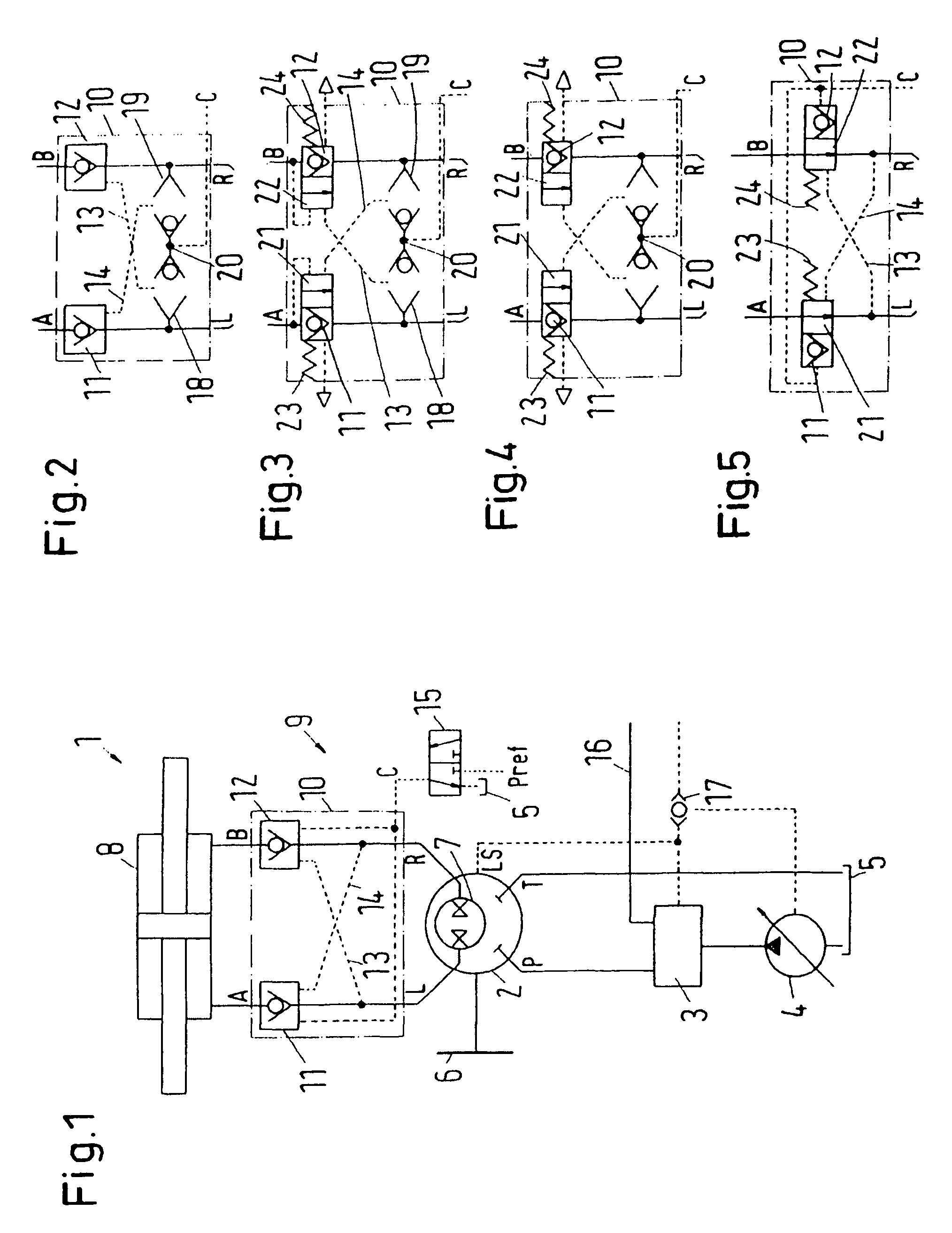
[0012]Preferably, for each working pipe the valve arrangement has a valve that interrupts the working pipe in a predetermined state. When the working pipe is interrupted, a feedback of the steering motor upon the steering unit is no longer possible. When the valves are open, the desired feedback behaviour appears. The use of a valve in each working pipe has the advantage that the steering behaviour and also the feedback behaviour are “symmetrical”, as the lengths of the hydraulic pipes, which can change their volume when acted upon by a pressure, correspond to each other, when a corresponding valve is located in each working pipe.
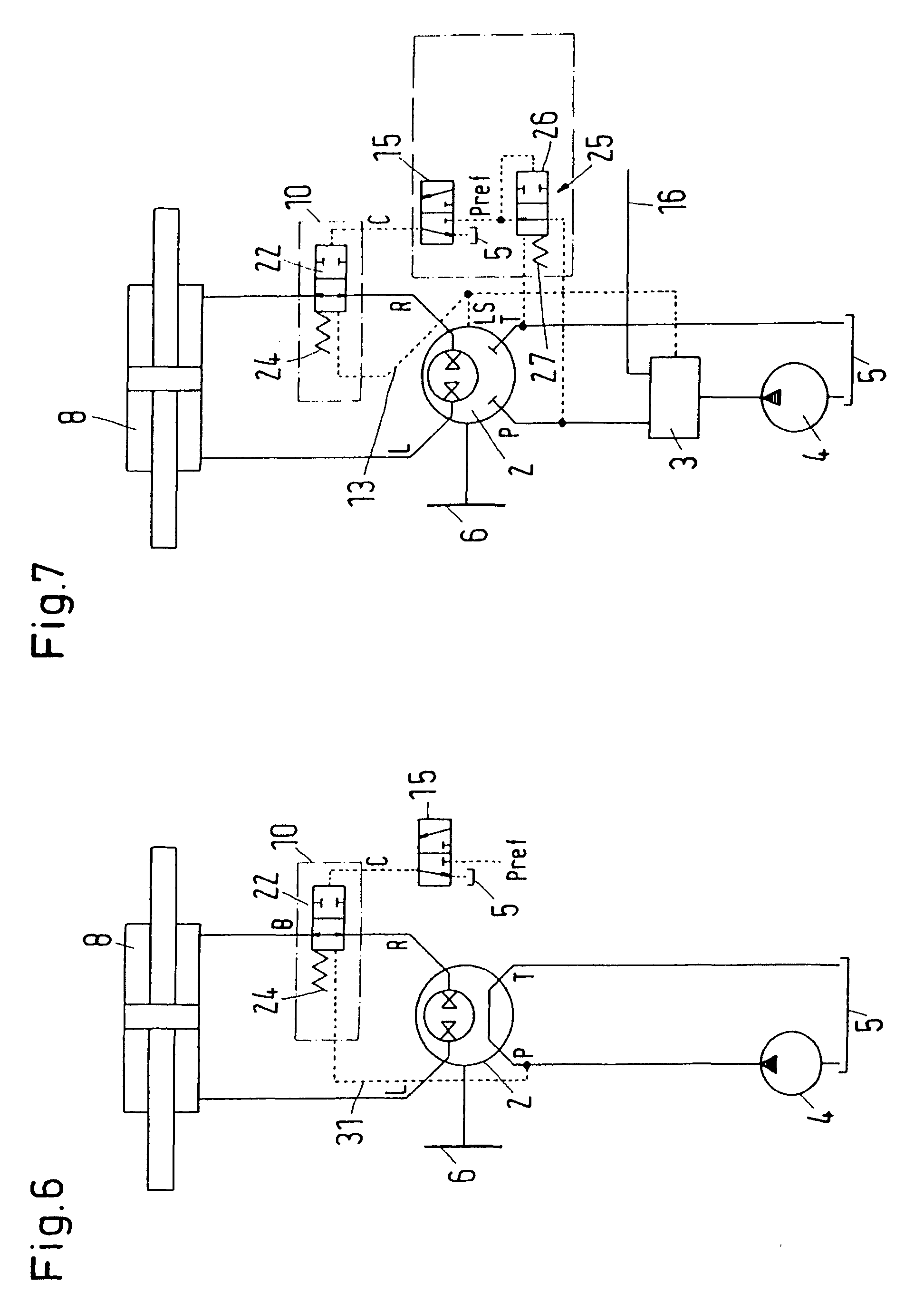
[0015]Preferably, a power assisted steering valve is connected in parallel to the steering unit, the steering valve being connected to the working pipes in an area between the feedback suppression device and the steering motor. The vehicle can then not only be controlled via the steering unit, but also via the steering valve. The steering valve can, for example, be a proportional valve. When the steering motor is controlled via the steering valve, the feedback suppression device is particularly advantageous, as it can prevent a movement of the steering member, which is caused by the activation of the steering motor by the steering valve.
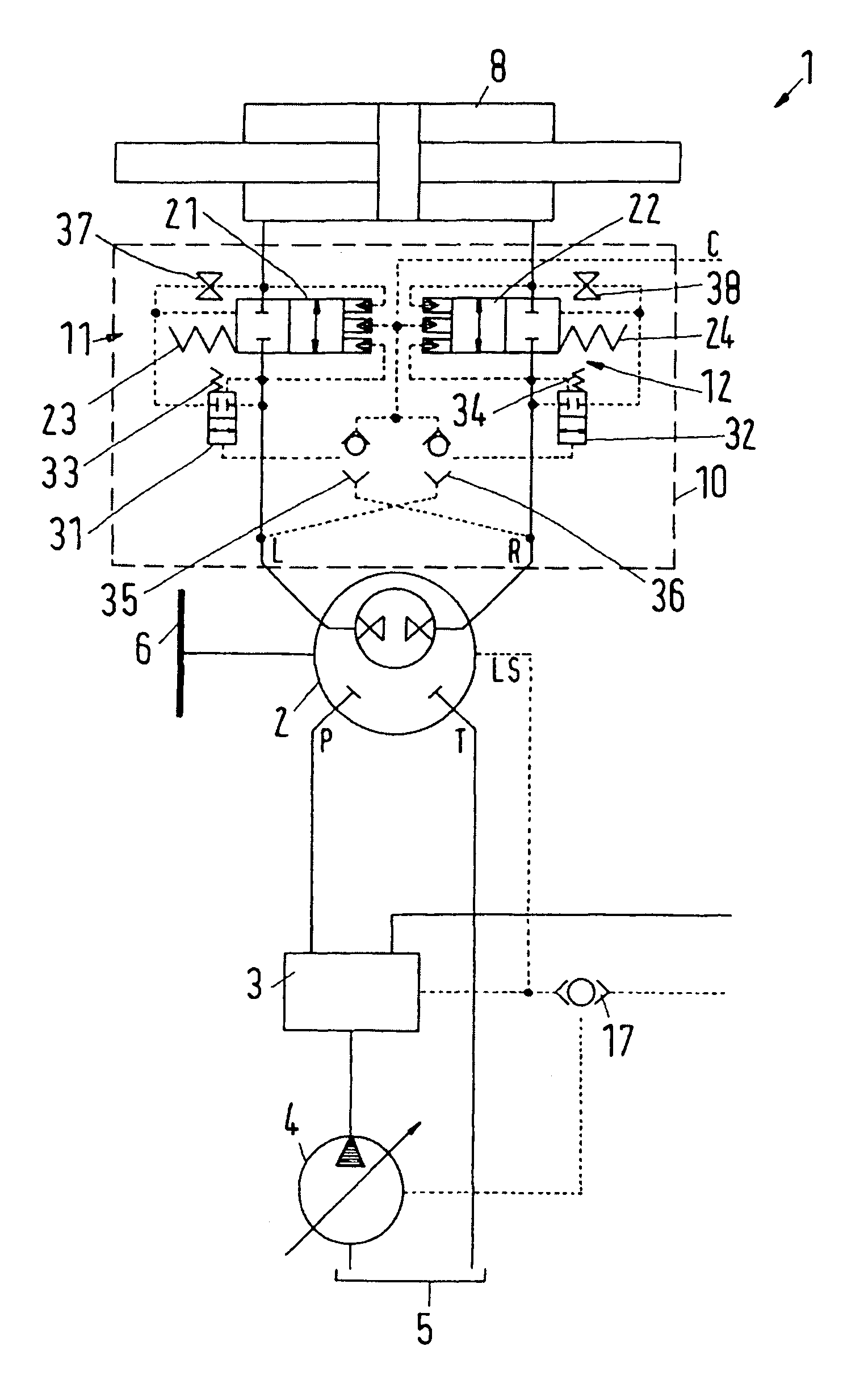
[0017]Preferably, the steering unit has a load-sensing connection, whose pressure acts upon the valve arrangement against the pressure at the control inlet. Thus, by means of the pressure at the load-sensing connection the effect of the pressure on the control inlet can be neutralized again. As soon as the driver activates the steering member, for example the steering handwheel, thus activating the steering unit, a higher pressure occurs at the load-sensing connection, which usually corresponds to the highest pressure available at the steering unit. In a simple manner, this pressure is able to override the pressure at the control inlet, either directly or indirectly.
[0018]It is particularly preferred that the load-sensing connection is connected to an auxiliary valve that is located between a pilot control pipe and a connection with a higher pressure. The connection with the higher pressure can be the supply connection or the high-pressure connection of the steering unit. In this case, the activation of the valve arrangement will cause no large “consumption” of hydraulic fluid. Such consumption could cause a “hard point” in the steering. When the pressure at the load-sensing connection acts upon the auxiliary valve, only a small amount of hydraulic fluid is required to deflect the auxiliary valve or to change its position. This small amount can practically not be felt by the driver or operator. The auxiliary valve has the further advantage that the pressure at the load-sensing connection in the neutral position does not have to be set exactly at the lowest pressure or tank pressure, when the auxiliary valve has a spring or another resetting device acting against the pressure at the load-sensing connection. The pressure at the load-sensing connection would then at least have to overcome the force of the resetting device, before the auxiliary valve is opened.
[0019]Preferably, the steering unit has a working pressure connection, relieved in the neutral position of the steering unit to a low-pressure connection and carrying at a predetermined deflection of the steering unit the pressure ruling in the controlled working pipe, a pressure at the working pressure connection acting upon the valve arrangement against the pressure at the control inlet. The pressure at the working pressure connection is also called “S-pressure” or “S-signal”. A steering unit with such a working pressure connection is available at Sauer-Danfoss ApS, Nordborg, Denmark, under the name of OSP-EL. This S-signal has the property that, in the neutral position and in a small band around the neutral position, it is relieved to tank or another area with a low pressure. When deflecting to the left or to the right, the S-signal always receives the pressure available at the outlet side of the set of teeth of the steering unit, that is, practically the pressure available in the “left” or “right” working pipe. Thus, a hard point in the steering is avoided, as no hydraulic fluid is consumed by the load-sensing connection. Further, a clearly defined “non-feedback state” is available, as in the neutral position the S-signal is effectively set at the tank pressure. Further, the concept offers an advantage in the emergency steering situation, where a pressure built up in one of the two working pipes will provide an additional certainty for the forced opening of the valve unit.

