Cyclonic chamber for air filtration devices

a technology of air filtration device and cyclonic chamber, which is applied in the field of vacuums, can solve the problems of affecting the vacuum strength, affecting the life of the conventional vacuum, and reducing the overall strength of the vacuum

Inactive Publication Date: 2010-09-07
WAI LAU YING
View PDF18 Cites 23 Cited by
  • Summary
  • Abstract
  • Description
  • Claims
  • Application Information

AI Technical Summary

Benefits of technology

[0014]It is another object of the invention to provide a cyclonic vacuum wherein the interior of the cyclonic chamber is substantially smooth.
[0015]It is still another object of the invention to provide a cyclonic vacuum wherein the interior of the cyclonic chamber is substantially free of obstructions.

Problems solved by technology

This tends to both prolong the life of the conventional filter and prevent a decline in the overall strength of the vacuum as the filter clogs.
However, many cyclonic designs impede vacuum strength.
However, the hard turn in the air path necessarily slows the flow of air as it enters the cyclonic chamber.
The length of the passage through which air must pass increases resistance, slowing the air and weakening the strength of the vacuum.
Thus, the addition of attachments to any vacuum will reduce its strength.
These vacuums have their own associated problems.
However, because the body of the nozzle itself extends into the cyclonic chamber, it acts as a physical obstruction to the cyclonic motion of the air.
This in turn substantially inhibits and / or destroys the cyclonic motion and slows the flow of the air.
As a result, the suction strength of the vacuum is weakened.

Method used


Image

  • Cyclonic chamber for air filtration devices
  • Cyclonic chamber for air filtration devices
  • Cyclonic chamber for air filtration devices

Examples


Embodiment Construction

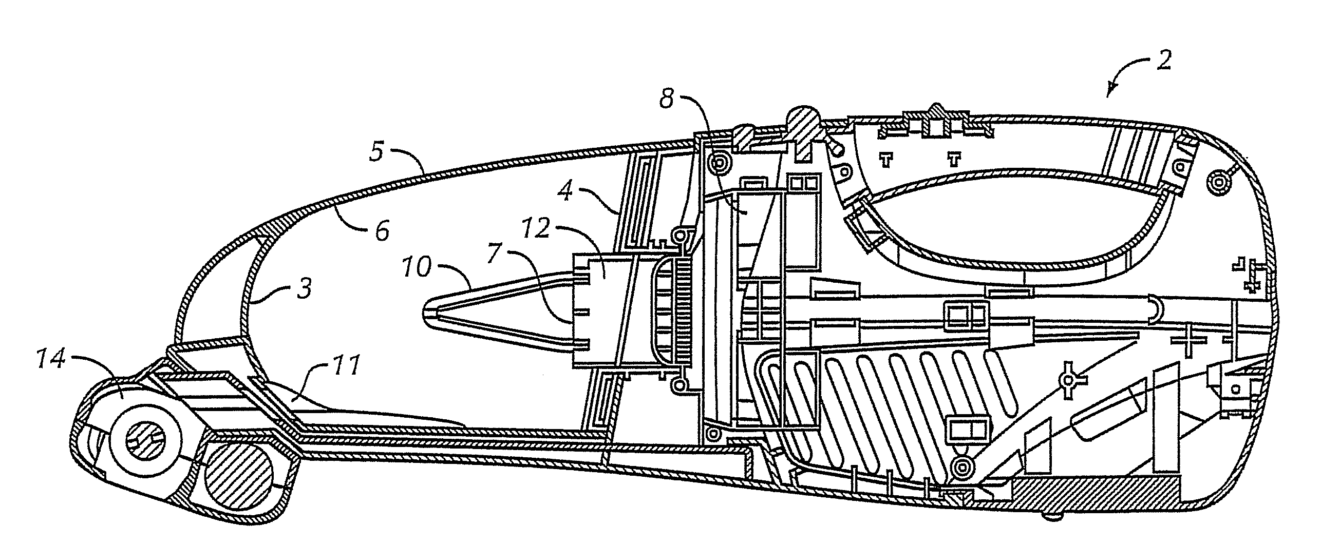
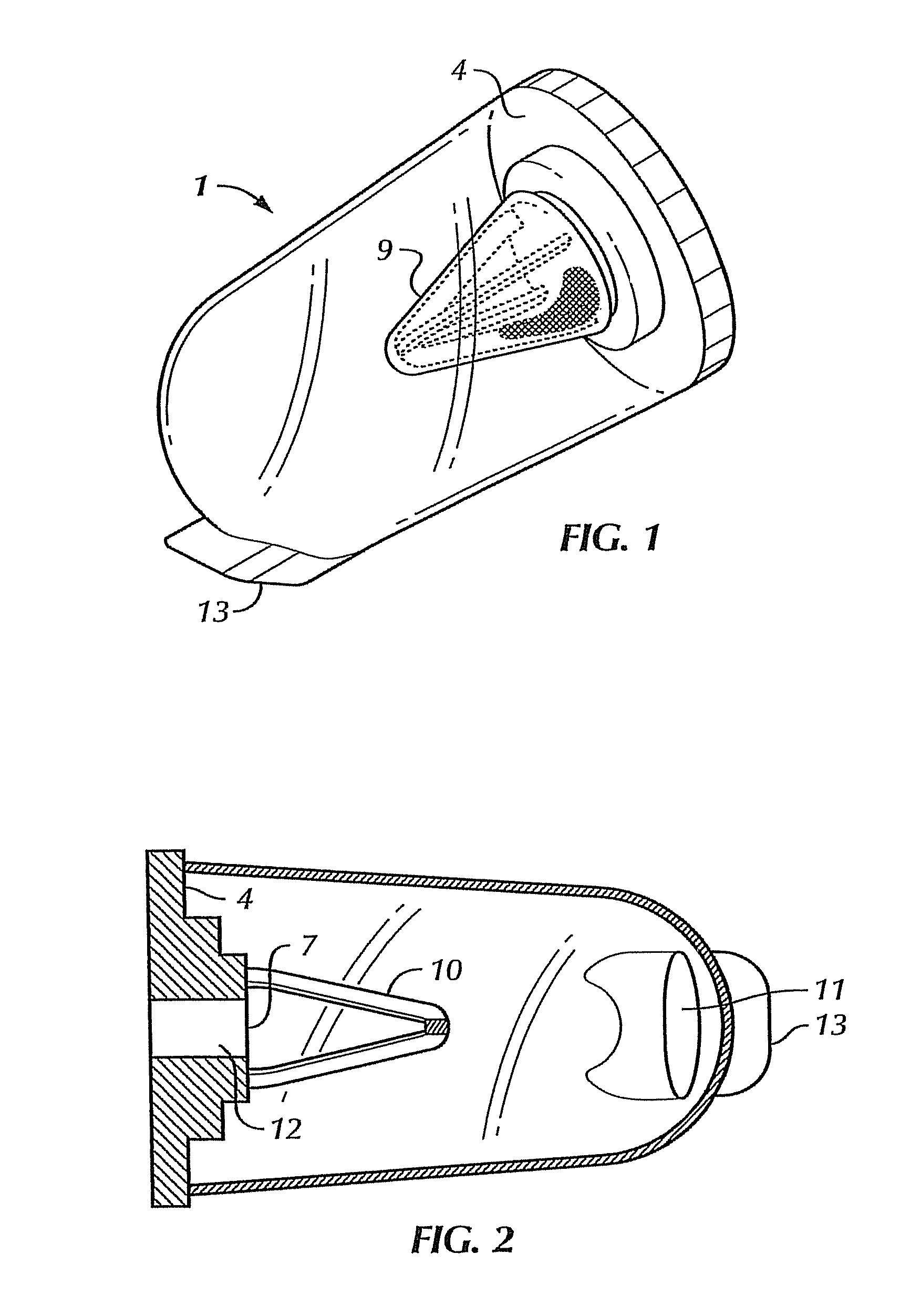
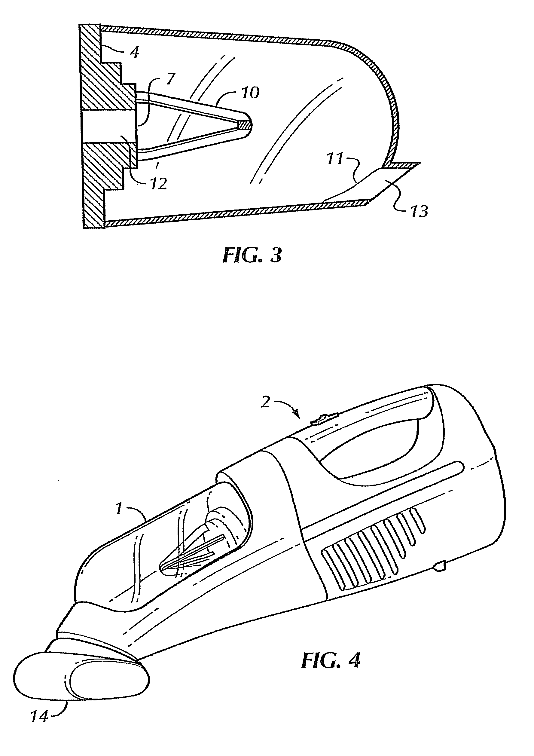
[0035]The invention comprises a cyclonic chamber 1 for a vacuum 2. A first preferred embodiment of chamber 1 will be discussed, followed by a second preferred construction. In a first preferred construction, cyclonic chamber 1 has an apex 3 opposite a base 4 and walls 5 extending therebetween. Cyclonic chamber 1 is either generally parabolic in cross section or generally tubular with a hemi-spherical cap at the apex end. The interior surface 6 of walls 5 and apex 3 are substantially smooth and free of obstructions. Extending inwardly from base 4 is an outflow passage 12, which terminates in an outflow aperture 7 that allows air to exit cyclonic chamber 1. Outflow passage 12 will preferably separate outflow aperture 7 from base 4. In the preferred embodiment, outflow aperture 7 will lead to a fan 8 which will generate suction for vacuum 2. Positioned over outflow passage 12 and outflow aperture 7 and extending into cyclonic chamber 1 is a filter 9. Filter 9 will preferably be conical...


PUM

PropertyMeasurementUnit
curvatureaaaaaaaaaa
angleaaaaaaaaaa
shapeaaaaaaaaaa

Abstract

A cyclonic chamber for use in air filtration devices. The chamber includes an apex opposite a base with sidewalls extending therebetween. The cyclonic chamber is preferably parabolic in cross-section or tubular with a hemi-spherical cap. The base contains an outflow passage and a conical filter extending therefrom. An inflow passage is provided proximate the apex. The inflow and outflow passages are parallel but not aligned. The chamber interior is smooth. The smooth interior and offset relationship of the inflow and outflow passages causes air to take a cyclonic path between the inflow passage and the filter. Debris in the airstream is pushed outward—away from the filter—by centripetal force. Eddies form proximate the base. Debris escapes the airstream there, where it either remains or, depending upon the chamber's orientation relative to gravity, falls back into the airflow where it is again directed away from the filter.

Description

CROSS-REFERENCE TO RELATED APPLICATIONS[0001]This application is a continuation-in-part of pending U.S. patent application Ser. No. 12 / 800,569, filed Apr. 9, 2009 which is hereby incorporated by reference in its entirety.BACKGROUND OF THE INVENTION[0002]1. Field of the Invention[0003]The invention relates to vacuums in general and to cyclonic vacuums in particular.[0004]2. Prior Art[0005]Cyclonic vacuums are well know in the art. For example, U.S. Pat. No. 4,373,228 to Dyson discloses a cyclonic vacuum. Such vacuums offer advantages over traditional vacuums in that they either require no conventional filter or, more commonly, the cyclonic action keeps dust and dirt away from the conventional filter, thereby preventing it from clogging. This tends to both prolong the life of the conventional filter and prevent a decline in the overall strength of the vacuum as the filter clogs. However, many cyclonic designs impede vacuum strength. In most cyclonic designs, cyclonic motion is imparte...

Claims


Application Information

Patent Timeline
Patent Type & Authority Patents(United States)
IPC IPC(8): B01D50/00
CPCA47L9/1608A47L9/1666B01D45/16B01D46/02B01D46/521B01D50/002B01D2279/55B04C2009/004Y10S55/03B01D50/20
Inventor WAI, LAU YING
Owner WAI LAU YING
Why Eureka
Try Eureka