
Locking device for automobile tray

a technology for automobiles and locking devices, which is applied in the direction of locking applications, carpet fasteners, mechanical devices, etc., can solve the problems that the latch b>3/b> may not be completely released, and achieve the effect of short operating distance, convenient opening of the tray, and sufficient vertical movement distan

Active Publication Date: 2010-10-05
HYUNDAI MOBIS CO LTD
View PDF7 Cites 18 Cited by
  • Summary
  • Abstract
  • Description
  • Claims
  • Application Information

AI Technical Summary

Benefits of technology

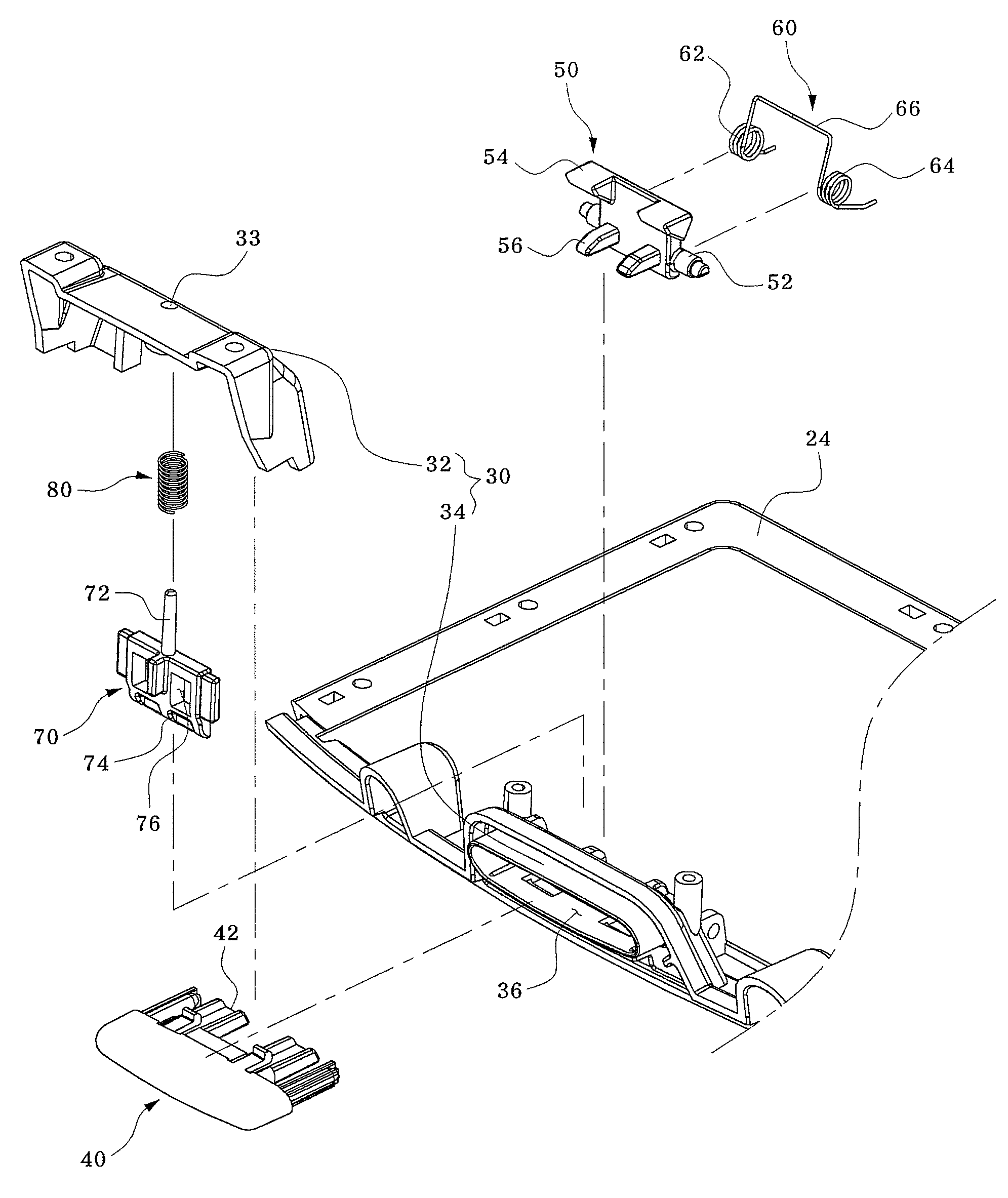
The present invention provides a locking device for an automobile tray that allows for efficient opening of the tray even with a short operating distance. The device includes an inner housing, an outer housing, a mount member, a knob, a rotating member, a first elastic member, a latch member, and a second elastic member. The knob is linearly moved into the operating opening by the user's manual operation, and the rotating member is rotated by the knob. The latch member is moved upward by the rotating member so as to be released from the holding recess, and the second elastic member provides the latch member with an elastic restoration force to allow it to be returned downward through the bottom opening of the mount member. The invention also allows for individual regulation of the operating forces of the knob and the latch, preventing degradation in their operation characteristics.

Problems solved by technology

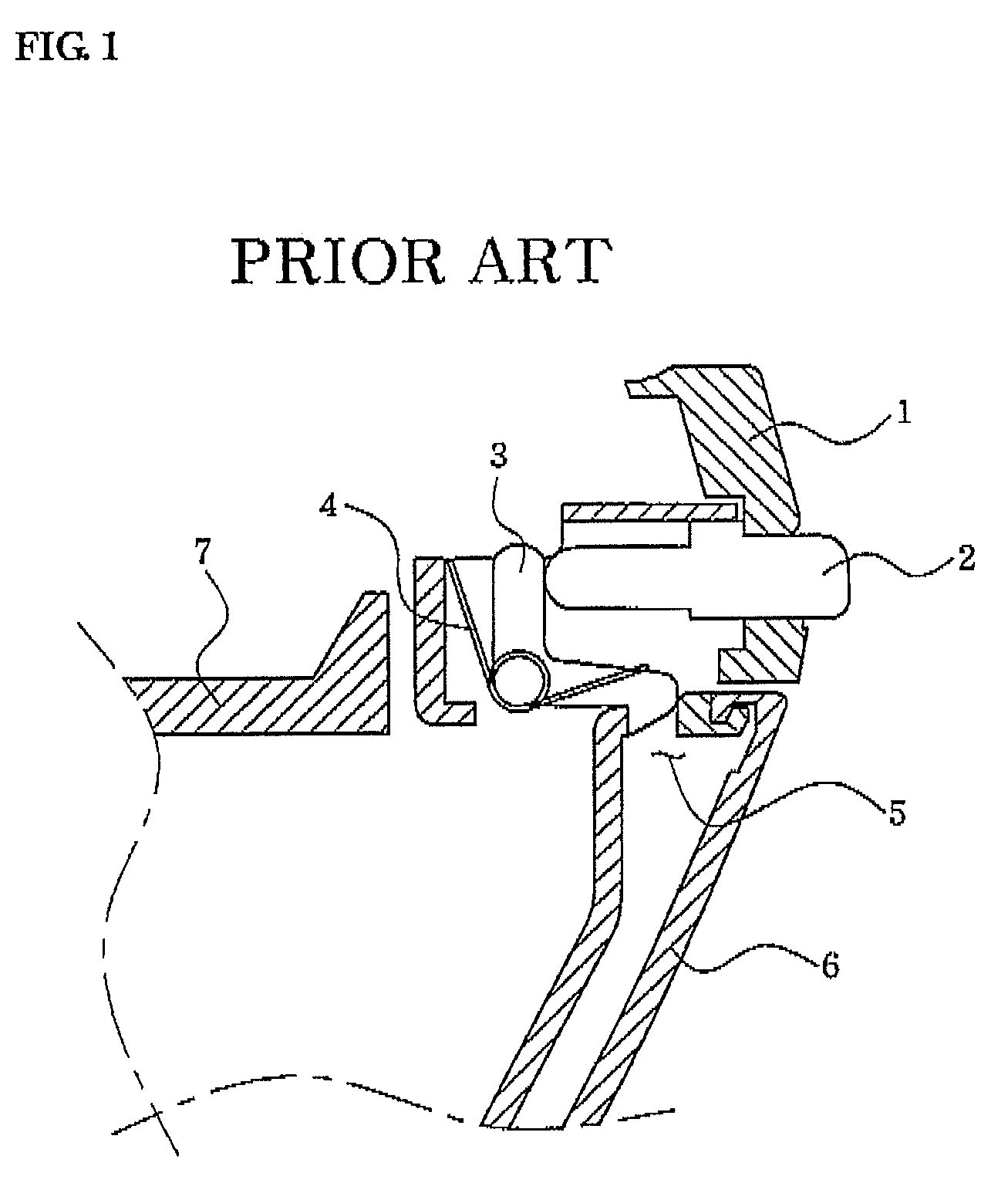
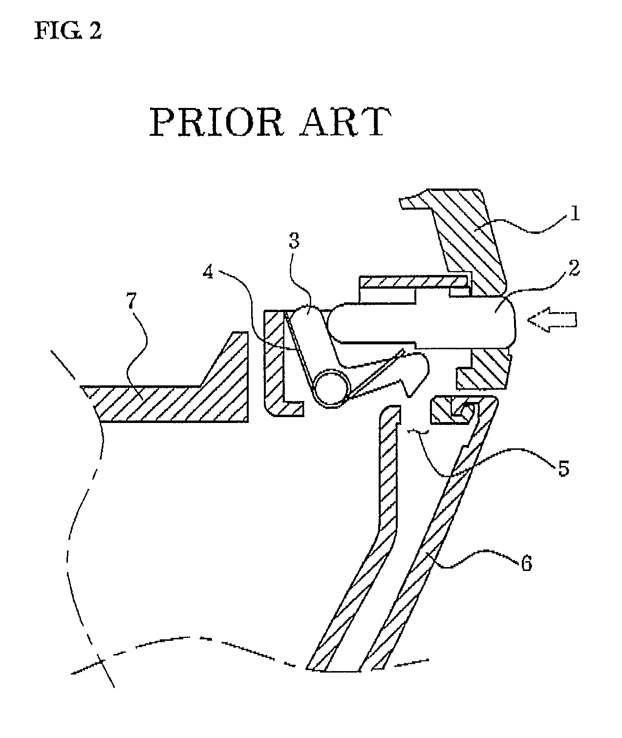
This is problematic because the latch 3 may fail to be completely released from the holding aperture 5.

Method used


Image

  • Locking device for automobile tray
  • Locking device for automobile tray
  • Locking device for automobile tray

Examples


Embodiment Construction

[0035]Now, a locking device for an automobile tray according to an exemplary embodiment of the present invention will now be described in detail with reference to the accompanying drawings. For the sake of convenience for explanation, a tray mounted in an automobile is exemplified, and the thickness of lines or the size of constituent elements shown in the drawings may be illustrated exaggeratingly for the clarity and convenience of description. Also, the terms of constituent elements, which will be described hereinafter, are defined in consideration of their functions in the present invention and may be changed according to the intention of a user or an operator, or according to the custom. Accordingly, definitions of these terms must be based on the overall description herein.

[0036]As shown in FIGS. 3 to 6, the automobile tray locking device according to the present invention includes an outer housing 20 defining an outer body and an inner housing 10 slidably operable in the outer...


PUM


Abstract

A locking device for an automobile tray is disclosed. The locking device includes an inner housing having a front panel formed with a holding recess, an outer housing internally defining an operating space for sliding movement of the inner housing therein, a mount member having a bottom opening for communicating with the holding recess and a front operating opening, a knob partially protruded outward through the operating opening of the mount member, the knob being linearly moved into the operating opening by the user's operation, a rotating member having a hinge shaft connected to the mount member so as to be rotated by the knob, a first elastic member having one end supported by the mount member and the other end supported by the rotating member, to provide the rotating member with an elastic restoration force so as to return the rotating member to its original position, a latch member configured to be caught by one end of the rotating member, the latch member being moved upward by the rotating member so as to be released from the holding recess, and a second elastic member installed between the latch member and the mount member and adapted to provide the latch member with an elastic restoration force so as to allow the latch member to be returned downward through the bottom opening of the mount member.

Description

BACKGROUND OF THE INVENTION[0001]1. Field of the Invention[0002]The present invention relates to an automobile tray, and more particularly, to a locking device for an automobile tray wherein a horizontal movement of a knob, which is manually operated to open the tray, is converted into a rotating movement of a rotating member and in turn, the rotating movement of the rotating member is converted into a vertical movement of a latch member, whereby locking and unlocking of the tray can be easily accomplished even in a limited space.[0003]2. Description of the Related Art[0004]Generally, an automobile contains several storage places therein for storing a variety of large and small items.[0005]Examples of the automobile storage spaces include a trunk room, which is suitable for storing relatively large items and allows the stored items to be taken out at the outside of an automobile, and an automobile tray which is suitable for storing relatively small and light-weight items and allows ...

Claims


Application Information

Patent Timeline
Patent Type & Authority Patents(United States)
IPC IPC(8): E05C1/12
CPCB60R7/06E05B83/30E05C1/14E05C3/162E05B63/0052Y10S292/37Y10T292/096Y10T292/097Y10T292/0971B60R7/04
Inventor OH, YOUNG KI
Owner HYUNDAI MOBIS CO LTD
Learn More