Vehicle

a technology for vehicles and radiators, applied in the field of vehicles, can solve the problems of insufficient running air in the radiator, and the space required for gas tank maintenance being not guaranteed, and achieve the effect of increasing the cooling efficiency of each radiator and increasing the cooling efficiency of the radiator

Inactive Publication Date: 2008-01-10
TOYOTA JIDOSHA KK
View PDF7 Cites 13 Cited by
  • Summary
  • Abstract
  • Description
  • Claims
  • Application Information

AI Technical Summary

Benefits of technology

[0018] In the second vehicle of the present invention, the gas fuel tank is placed on the vehicle body roof, the radiator for a power source is placed on the rear of the gas fuel. tank, and the roof cover that covers the vehicle body roof has the upper outside air introducing opening that introduces to the radiator the outside air (running air) passing through the upper side with running of the vehicle. Thus, the radiator can be cooled using outside air passing through the upper side of the gas fuel tank. This can increase cooling efficiency of the radiator for a power source while ensuring a space for placement of the gas fuel tank. Also, the upper outside air introducing opening is provided on the rear of the gas fuel tank, and thus gas fuel leaking from the gas fuel tank can be diluted using the outside air introduced into the upper outside air introducing opening. The upper outside air introducing opening that introduces the outside air passing through the upper side to the radiator, which is because if a side outside air introducing opening is provided that introduces outside air passing through a lateral side into a radiator, the outside air needs to be introduced from as far forward as possible (the side closer to the gas fuel tank) for sufficiently introducing the outside air passing through the lateral side, which reduces spaces near opposite ends in a vehicle width direction of a gas fuel tank, while the outside air passing through the upper side is introduced to allow sufficient outside air to be introduced and ensure a maintenance space for the gas fuel tank. In this case, the gas fuel tank may be horizontally placed on the vehicle body roof so that a longitudinal direction thereof is in a vehicle width direction, may be horizontally placed on the vehicle body roof so that the longitudinal direction thereof is in the vehicle fore / aft direction, or may be vertically placed on the vehicle body roof so that the longitudinal direction thereof is in the vehicle width direction or the vehicle fore / aft direction. The gas fuel tank may have a substantially cylindrical shape.
[0019] In the second vehicle of the present invention, the roof cover may have a downward inclined surface descending from the portion above the gas fuel tank placed at the rearmost portion in the vehicle fore / aft direction to a lower end of the upper outside air introducing opening. This allows the outside air to be guided into the upper outside air introducing opening effectively using the shape of the substantially cylindrical gas fuel tank. In this case, the roof cover may have wall portions on opposite sides of the downward inclined surface in the vehicle width direction. This allows the outside air to be guided into the upper outside air introducing opening more properly.
[0020] In the second vehicle of the present invention, it may be allowed that a plurality of radiators are arranged in the vehicle fore / aft direction, the upper outside air introducing opening of the roof cover introduces outside air to a radiator placed on the front side among the plurality of radiators, and the roof cover has, in a side portion thereof, a side outside air introducing opening that opens so as to introduce outside air passing through a lateral side with running of the vehicle to a radiator placed on the rear side among the plurality of radiators. This allows the plurality of radiators to be placed in a compact manner and increases cooling efficiency of each radiator. In this case, it may be allowed that two radiators are arranged on the front side in the vehicle width direction and two radiators are arranged on the rear side in the vehicle width direction.

Problems solved by technology

In this case, the gas tank occupies most of a space on the roof, which may make it difficult to place a radiator in a position where sufficient running air can be introduced, or prevent a space required for maintenance of the gas tank from being ensured.

Method used


Image

  • Vehicle
  • Vehicle
  • Vehicle

Examples


Embodiment Construction

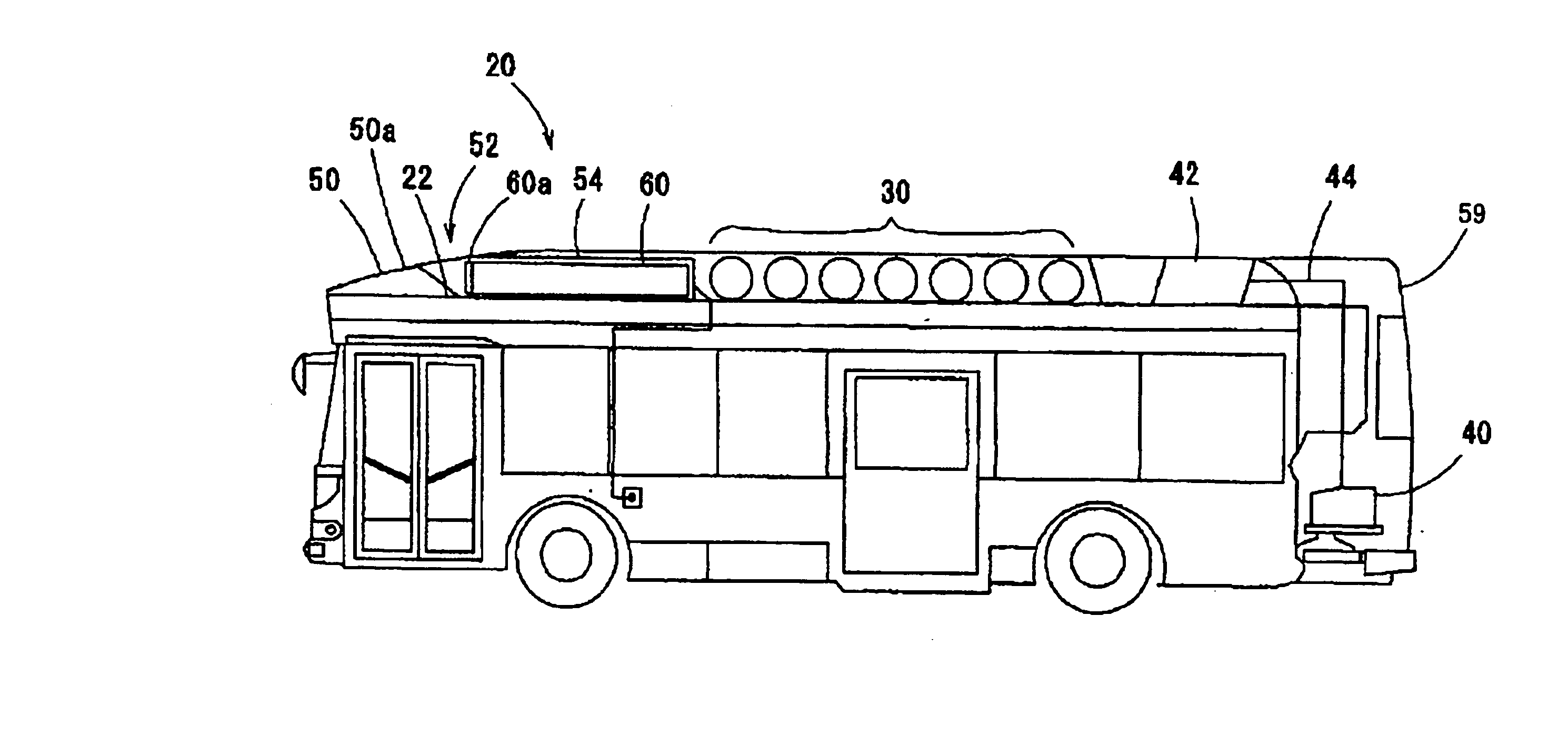
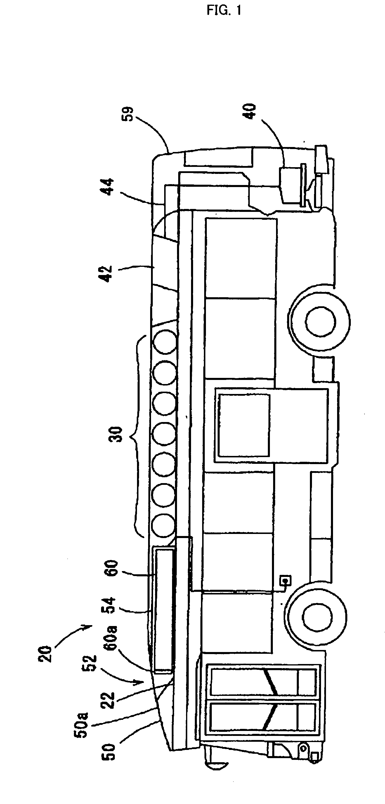
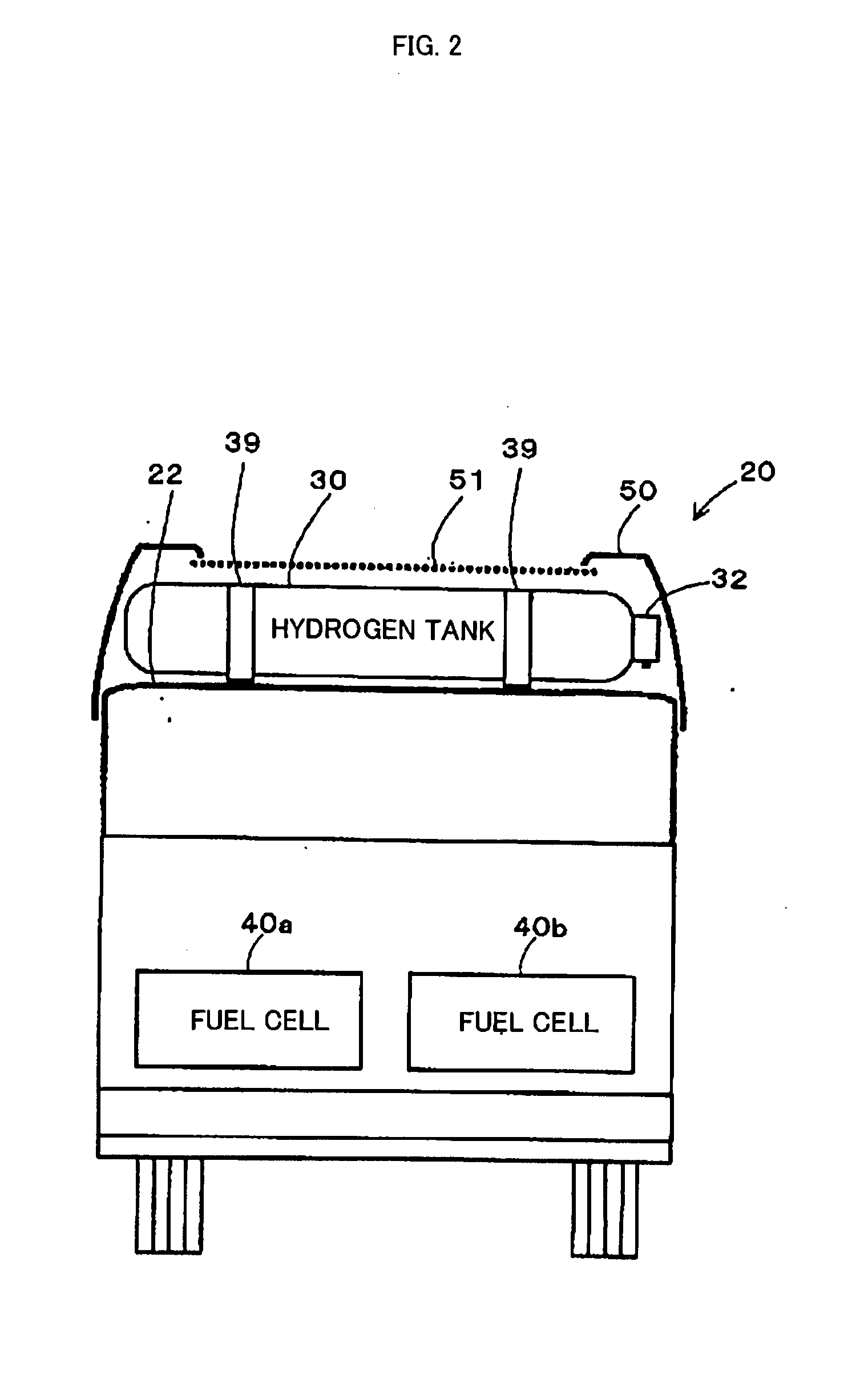
[0028] Now, the best mode for carrying out the invention will be described with reference to an embodiment. FIG. 1 is a schematic block diagram of a configuration of a fuel cell-equipped bus 20 according to an embodiment of the present invention, FIG. 2 illustrates a state in which fuel cells 40a and 40b and a hydrogen tank 30 are mounted in a rear portion and on a roof 22, respectively, of the fuel cell-equipped bus 20, FIG. 3 illustrates a region from a middle portion to a rear portion on the roof 22 of the fuel cell-equipped bus 20, and FIG. 4 illustrates placement of the hydrogen tank 30 or the like on the roof 22 of the fuel cell-equipped bus 20. As shown, the fuel cell-equipped bus 20 of the embodiment is. configured as a large bus that runs using the fuel cells 40a and 40b as a power source, and includes the fuel cells 40a and 40b in the rearmost portion thereof, and seven substantially cylindrical hydrogen tanks 30 that store hydrogen as fuel to be supplied to the fuel cells...


PUM


Abstract

A hydrogen tank is placed substantially at a middle portion in a fore/aft direction on a roof of a fuel cell-equipped bus, an air conditioning unit is placed on the front of the hydrogen tank and a radiator is placed on the rear thereof, and these components are covered with a roof cover. An outside air guiding portion that guides outside air to an outside air introducing opening of the air conditioning unit is provided in the middle of an upward inclined surface in a front portion of the roof cover and above a front portion of the air conditioning unit, and a partition wall portion that separates the hydrogen tank from the air conditioning unit is provided in the periphery of the air conditioning unit on the side of the hydrogen tank. Thus, hydrogen leaking from the hydrogen tank flows rearward by running air, and can be prevented from entering an occupant compartment through the outside air introducing opening of the air conditioning unit.

Description

TECHNICAL FIELD [0001] The present invention relates to a vehicle, and more particularly to a vehicle that runs using power from a power source. BACKGROUND ART [0002] A conventionally known vehicle of this type includes an engine using gas fuel such as CNG (compression natural gas). For using such a vehicle as, for example, a route bus, it is proposed to place a gas fuel cylinder on a roof in order to provide a low floor in terms of barrier-free access for the elderly (for example, see Japanese Patent Laid-Open No. 2001-239846). [0003] As a method for cooling a power source of a vehicle of this type, a fuel cell device is proposed in which a fuel cell as a power source and a radiator are connected by a cooling tube, and the radiator is placed to be exposed to outside air (for example, see Japanese Patent Laid-Open No. 2001-93556). When this device is mounted to, for example, an automobile, the radiator is placed below a wing of an air spoiler, and air collected by the air spoiler is...

Claims


Application Information

Patent Timeline
Patent Type & Authority Applications(United States)
IPC IPC(8): B60K15/067B60H1/00B62D31/02B60K11/04
CPCB60H1/00428B60H1/00371Y02T10/88
Inventor NAGANUMA, YOSHIAKI
Owner TOYOTA JIDOSHA KK
Why Eureka
Try Eureka