Laser angle guide assembly for computed tomography and method for operating the same

a technology of computed tomography and laser angle guide, which is applied in the direction of tomography, radiation beam directing means, applications, etc., can solve the problems of puncturing angle, pain to the patient, and patient complications

Inactive Publication Date: 2010-10-05
CHAN WING SHEUNG
View PDF6 Cites 3 Cited by
  • Summary
  • Abstract
  • Description
  • Claims
  • Application Information

AI Technical Summary

Benefits of technology

[0007]The main objective of the invention is to provide a laser angle guide assembly that can provide a guide effect to help a doctor to puncture a needle assembly at a desired angle precisely. The laser angle guide assembly has a stand, a laser guide and a reflector. The laser guide is mounted adjustably on the stand and has a body, a side index line, a front index line and an index protrusion. The body has a front face, two side faces, a top and a bottom. The side index line is formed on the side faces of the body. The front index line is formed on the front face of the body. The index protrusion is formed on the front surface at the bottom of the body and has an inclined top and a front face. The reflector is attached and inclined relative to the front surface of the laser guide at an angle and has a reflecting side facing to the inclined top of the index protrusion.

Problems solved by technology

However, there is no guide for the puncturing angle during the specimen process, so a laser angle guide assembly is provided to generate an index line to help a doctor to puncture the needle assembly into the patient's body.
If the puncturing angle has a large deviation relative to the desired puncturing angle, this will cause pain to the patient and even to lead complications to the patient.

Method used


Image

  • Laser angle guide assembly for computed tomography and method for operating the same
  • Laser angle guide assembly for computed tomography and method for operating the same
  • Laser angle guide assembly for computed tomography and method for operating the same

Examples


Embodiment Construction

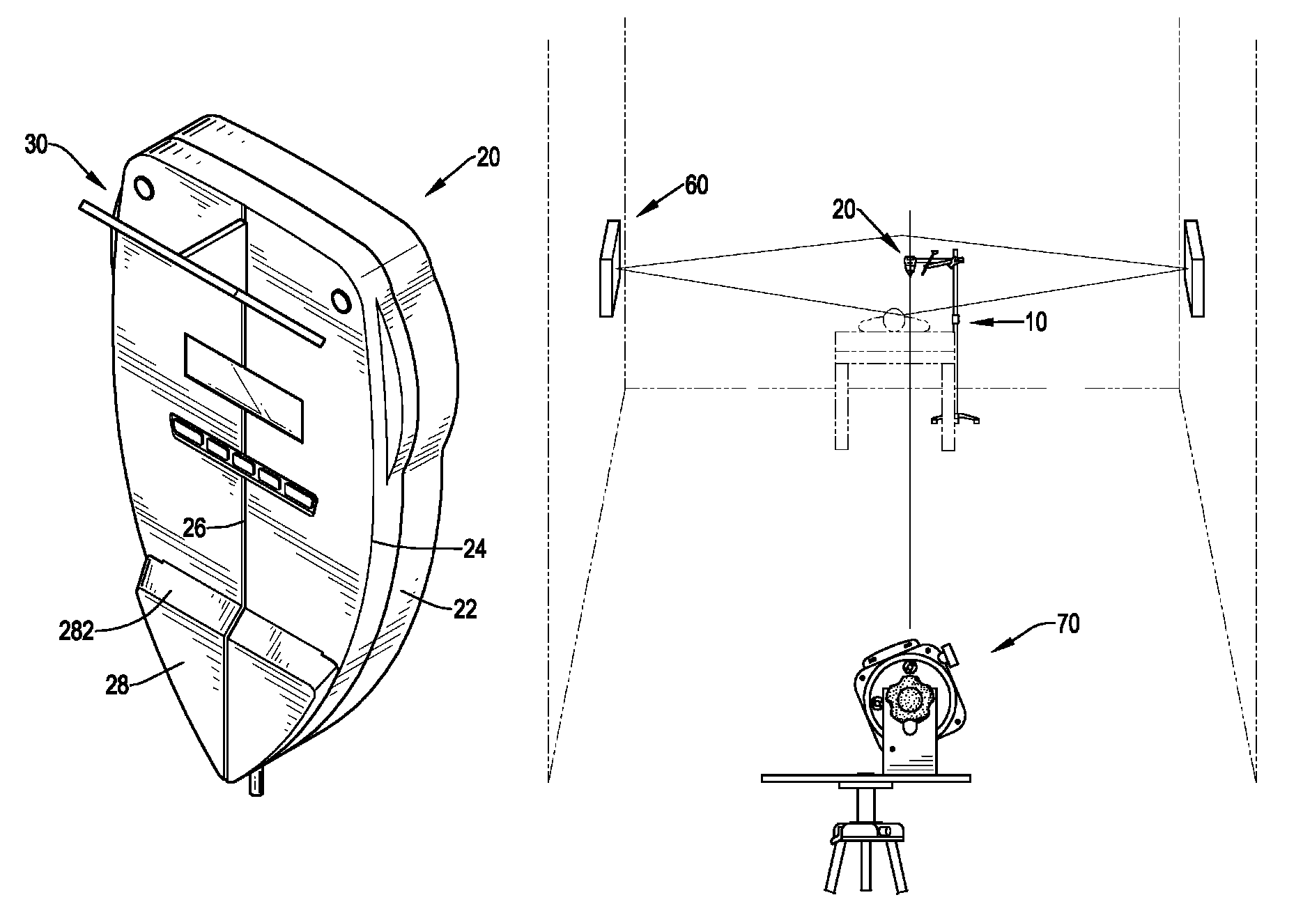
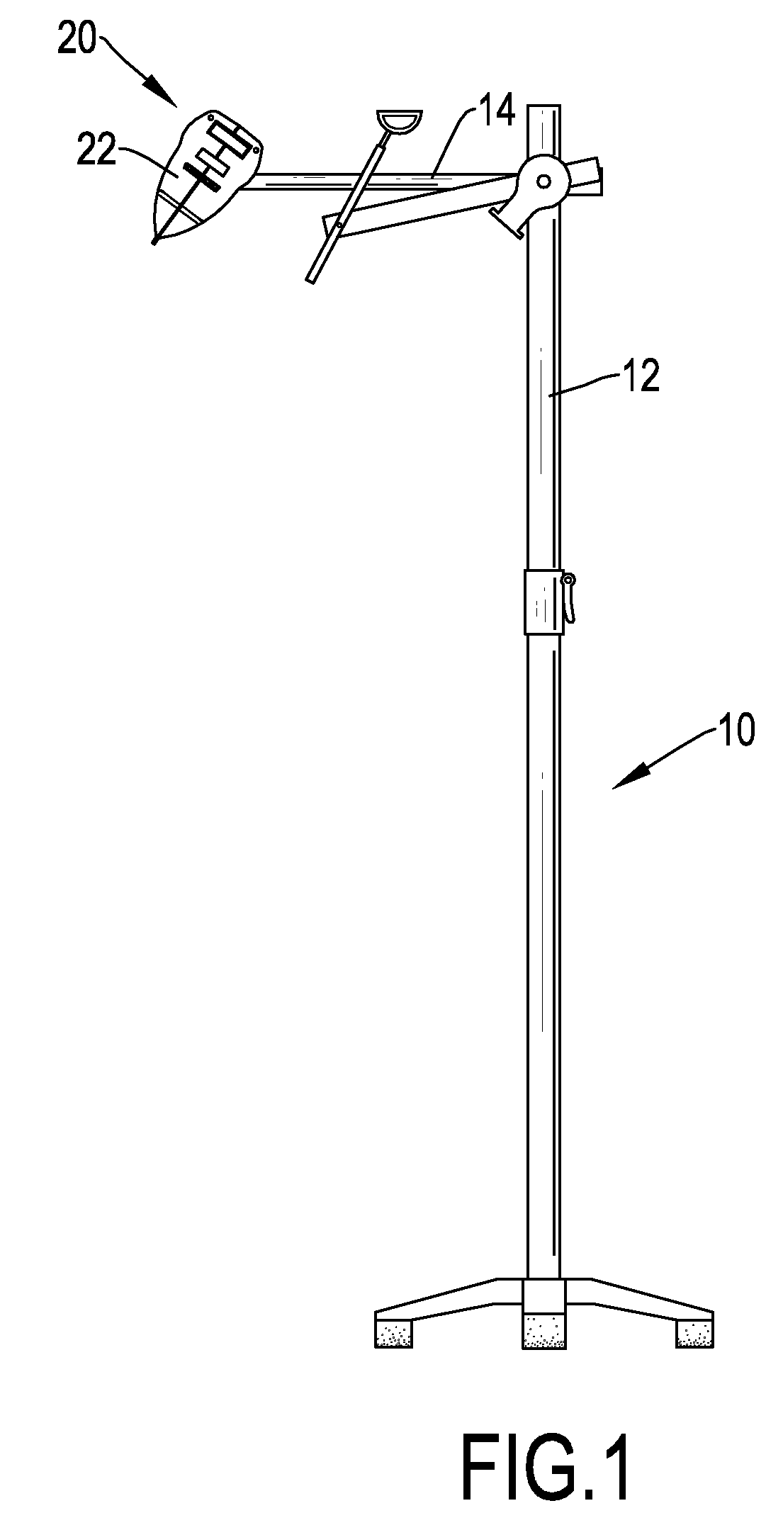
[0016]With reference to FIGS. 1 to 3, a laser angle guide assembly for a puncturing process with computed tomography (CT) in accordance with the present invention comprises a stand (10), a laser guide (20) and a reflector (30). The stand (10) comprises a base, a post (12) and a lateral rod (14). The post (12) is mounted on and protrudes upward from the base. The lateral rod (13) is laterally mounted near the top end of the post (12).

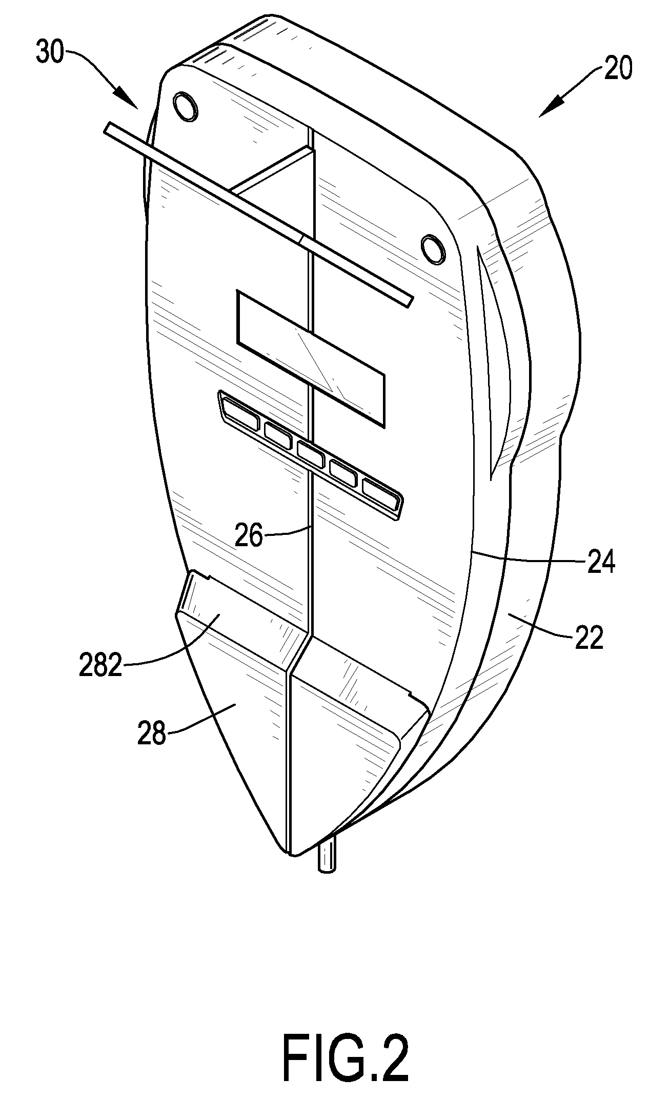
[0017]The laser guide (20) is mounted adjustably on the lateral rod (14) at angle. In practice, the laser guide (20) may be connected to the lateral rod (14) with a universal joint or at least one pivot pin that is rotatably mounted between the laser guide (20) and the lateral rod (14) to make the angle of the laser guide (20) adjustable relative to the lateral rod (14). The laser guide (20) has a body (22) having a front face, two side faces, two side edges, a top, a bottom, a side index line (24), a front index line (26) and an index protrusion (28). T...


PUM


Abstract

A laser angle guide assembly has a stand, a laser guide and a reflector. The laser guide is mounted adjustably on the stand and has a body, a side index line, a front index line and an index protrusion. The side index line is formed on the side faces of the body. The front index line is formed on the front face of the body. The index protrusion is formed on the front surface at the bottom of the body and has an inclined top and a front face. The reflector is attached and inclined relative to the front surface of the laser guide at an angle and has a reflecting side facing to the inclined top of the index protrusion. Accordingly, the laser angle guide assembly can provide a guide effect to help a doctor to puncture a needle assembly at a desired angle precisely.

Description

BACKGROUND OF THE INVENTION[0001]1. Field of the Invention[0002]The present invention relates to a laser angle guide assembly, and more particularly to a laser angle guide assembly for computed tomography (CT) and a method for the same.[0003]2. Description of Related Art[0004]Computed tomography is a way to scan a patient for biopsy, and a specimen of tissue will be removed from the patient and be examined by a pathologist to check diseases, such as cancer. A doctor will remove a specimen of tissue from the patient with puncturing a needle assembly in to a patient's body at a desired position, angle and depth determined by the computed tomography. However, there is no guide for the puncturing angle during the specimen process, so a laser angle guide assembly is provided to generate an index line to help a doctor to puncture the needle assembly into the patient's body.[0005]However, during the puncturing process, the laser angle guide assembly has to be removed so that the angle for ...

Claims


Application Information

Patent Timeline
Patent Type & Authority Patents(United States)
IPC IPC(8): A61B6/08
CPCA61B19/201G01C15/002A61B6/03A61B2019/202A61B90/11A61B90/13
Inventor CHAN, WING-SHEUNG
Owner CHAN WING SHEUNG
Why Eureka
Try Eureka