Light emitting diode module with improved light distribution uniformity

a light-emitting diode and module technology, applied in the field of light sources, can solve the problems of poor light uniformity across the lens surface, poor light uniformity, and objectionable, and achieve the effect of improving light distribution uniformity

Active Publication Date: 2010-10-12
DIALIGHT CORP
View PDF20 Cites 30 Cited by
  • Summary
  • Abstract
  • Description
  • Claims
  • Application Information

AI Technical Summary

Benefits of technology

[0006]In one embodiment, the invention is a light emitting diode module with improved light distribution uniformity. One embodiment of a signal head includes a light emitting diode and a reflector cup positioned to reflect light emitted by the light emitting diode, the reflector cup having a non-symmetrical curvature.

Problems solved by technology

Traffic lights, rail lights and other signal heads often suffer from poor light uniformity across the lens surface.
Poor light uniformity is distracting and is typically considered objectionable.
This means that no area of the lens can be ten times brighter than any other area of the lens.
This gives a “pixelated” appearance which is often objectionable.

Method used


Image

  • Light emitting diode module with improved light distribution uniformity
  • Light emitting diode module with improved light distribution uniformity
  • Light emitting diode module with improved light distribution uniformity

Examples


second embodiment

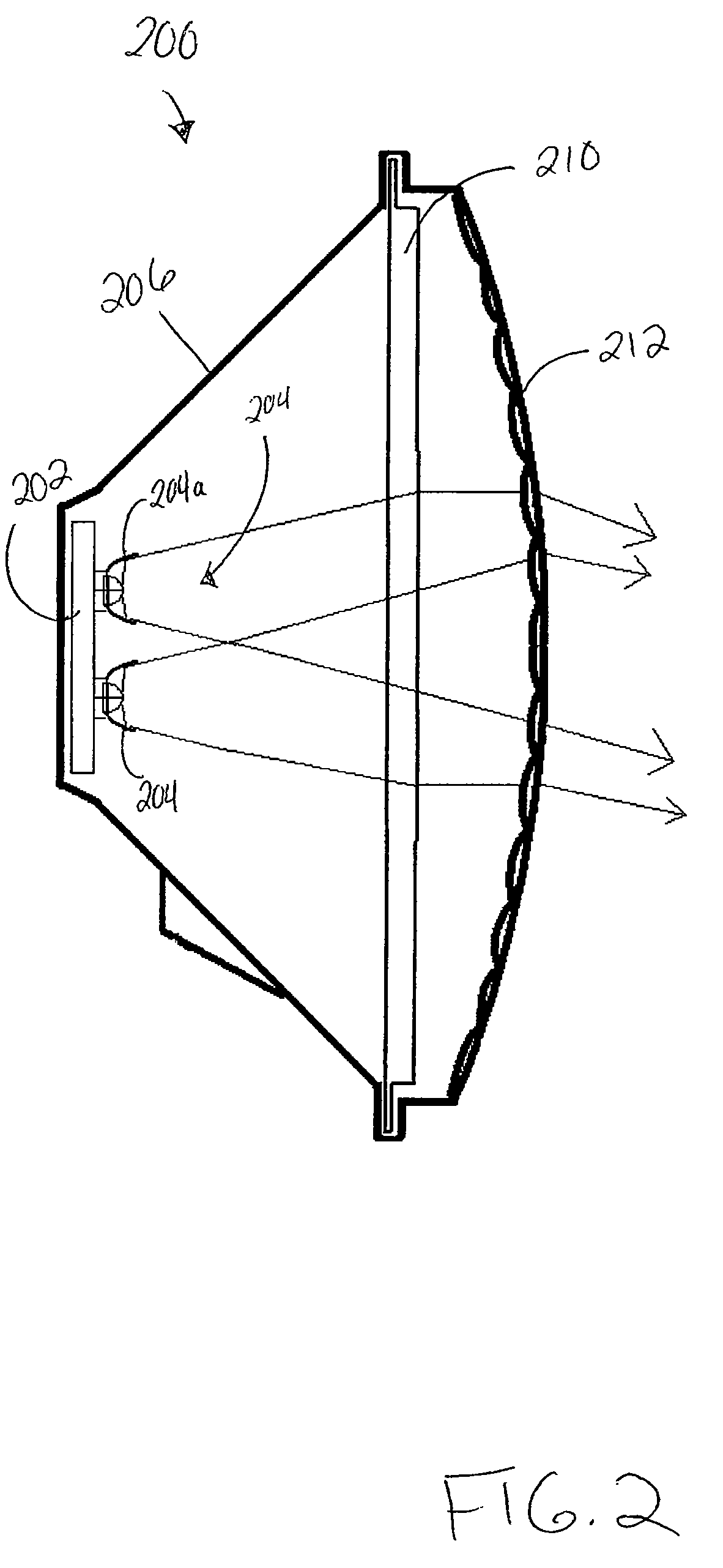
[0030]FIG. 2 depicts a traffic head assembly 200 that may be adapted to benefit from the present invention. Like the assembly 100, the assembly 200 comprises an LED array 202 comprising a plurality of LEDs and a reflector optic 204 surrounding the LED array 202. Specifically, as illustrated in more detail in FIG. 4, which depicts one embodiment of a reflector optic 204, the reflector optic 204 comprises a plurality of reflector cups 204a-204n, each reflector cup 204a-204n being positioned around an individual LED 400. The illustrated reflector cup 204a has revolved and surface symmetry. Referring back to FIG. 2, in one embodiment, the assembly 200 also comprises a housing 206, a Fresnel lens 210 and a spreading lens 212.

[0031]As illustrated, the LED array 202 and reflector optic 204 are configured so that light emitted by the LED array 202 is not tilted (i.e., is received substantially straight on or at a minimal angle by the Fresnel lens 210 and spreading lens 212). As a result, th...

third embodiment

[0034]In one embodiment, the reflector cups are not tilted, but rather have non-symmetric curvature in order to achieve the tilted reflector effect. FIG. 6A, for example, depicts a reflector optic 600a (i.e., reflector cup), in which the curvature of the reflector optic 600a is non-symmetric about a center axis 602a. That is, a first section 604a of the reflector optic's perimeter has a larger radius than a second section 606a of the reflector optic's perimeter. The non-symmetric curvatures may be “blended” together along the sidewalls of the reflector optic 600a. By altering the curvature of the reflecting surface non-symmetrically with respect to the center axis 602a, light is tilted / directed away from center axis 602a. In one embodiment, the curvature at any one point on the reflector optic 600a is between approximately zero degrees and approximately ninety degrees with respect to the center axis 602a. In one embodiment, the resultant tilt has a tolerance of ±10°.

fourth embodiment

[0035]FIG. 6B, on the other hand, depicts a reflector optic 600b (i.e., reflector cup), in which the slope of the reflector optic 600b is non-uniform. That is, a first section 604b of the reflector optic's perimeter has a higher slope than a second section 606b of the reflector optic's perimeter. For example, as illustrated, a first angle 608b between a vertical line and the slope of the first section 604b is less than a second angle 610b between the same vertical line and the second section 606b. In one embodiment, the second angle 608b is at least five degrees greater than the first angle 610b.

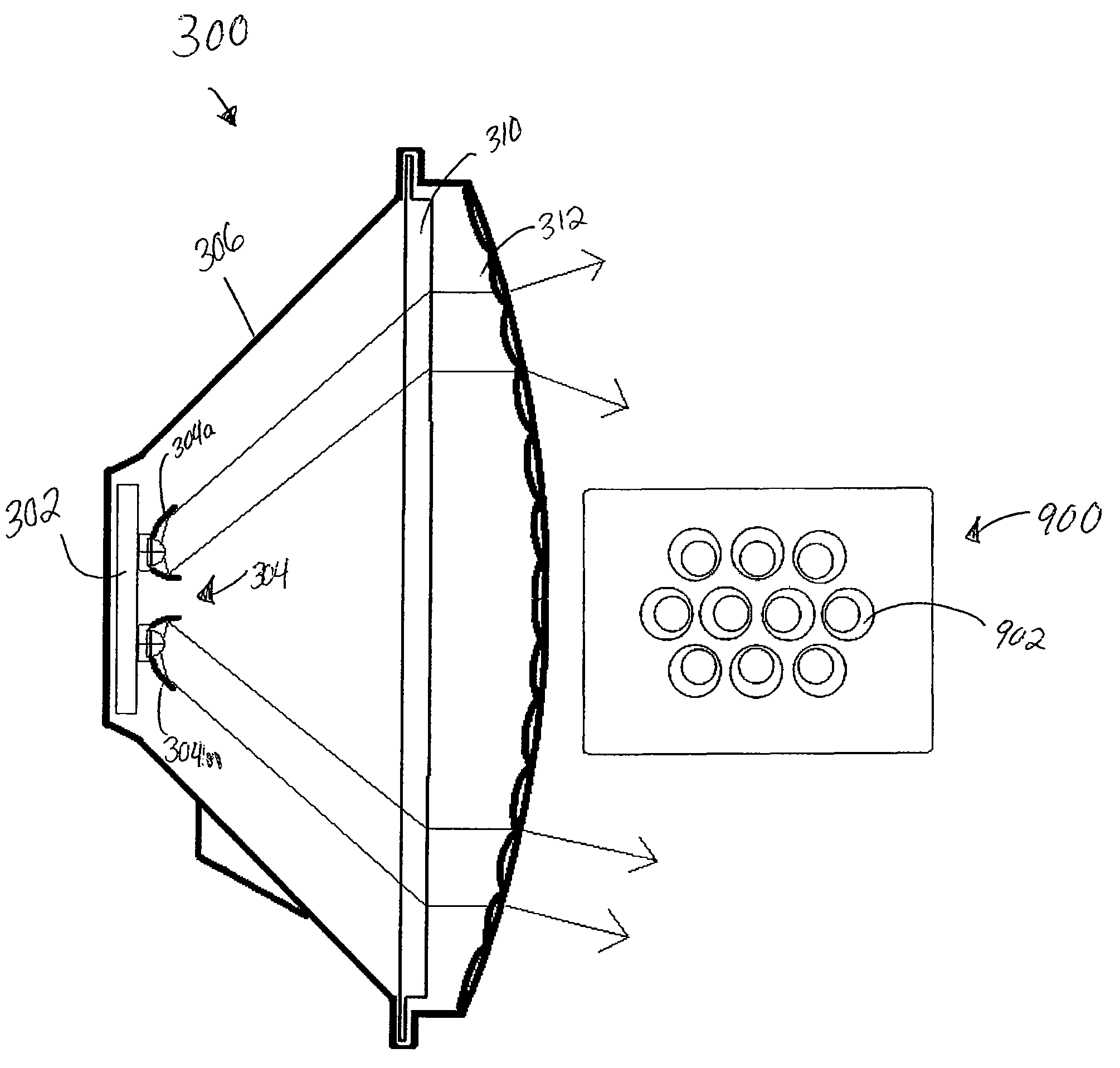
[0036]As illustrated in FIG. 9, which depicts an array 900 of reflector optics (i.e., reflector cups 902) with non-symmetric curvature, the reflector cups 902 can also be fanned out radially. In this case, the light / tilt angle can be a function of the position away from the central optical axis of a signal head assembly.

[0037]As discussed with respect to FIG. 6, one embodiment of an LED-bas...


PUM


Abstract

In one embodiment, the invention is a light emitting diode module with improved light distribution uniformity. One embodiment of a signal head includes a light emitting diode and a reflector cup positioned to reflect light emitted by the light emitting diode, the reflector cup having a non-symmetrical curvature.

Description

CROSS REFERENCE TO RELATED APPLICATIONS[0001]This application claims the benefit of U.S. Provisional Patent Application Ser. No. 60 / 781,241, filed Mar. 10, 2006, which is herein incorporated by reference in its entirety.BACKGROUND OF THE INVENTION[0002]The present invention relates generally to a light source, and relates more particularly to a light emitting diode (LED)-based signal head.[0003]Traffic lights, rail lights and other signal heads often suffer from poor light uniformity across the lens surface. Poor light uniformity is distracting and is typically considered objectionable. The Institute for Transportation Engineers (ITE) has recently set a lens luminance uniformity requirement for a round traffic ball of ten to one. This means that no area of the lens can be ten times brighter than any other area of the lens.[0004]In some traffic light designs, a large number of low-power LEDs are arranged uniformly across the traffic front of the signal head. This gives a “pixelated” ...

Claims


Application Information

Patent Timeline
Patent Type & Authority Patents(United States)
IPC IPC(8): F21V7/00
CPCF21K9/00F21V5/008F21V7/09F21V13/04F21V5/02F21V5/045F21V7/0091F21W2111/02F21Y2101/02B61L2207/02B61L5/1827B61L5/1845B61L5/1854F21Y2115/10F21K9/68
Inventor PECK, JOHN PATRICK
Owner DIALIGHT CORP
Why Eureka
Try Eureka