Terminal fitting with a wire restriction

a technology of terminal fittings and restriction points, applied in the direction of electrical equipment, contact parts, connections effected by permanent deformation, etc., can solve the problem of reducing the strength of the terminal fittings, and achieve the effect of improving the connection between wires and terminal fittings

Inactive Publication Date: 2010-10-12
SUMITOMO WIRING SYST LTD
View PDF7 Cites 12 Cited by
  • Summary
  • Abstract
  • Description
  • Claims
  • Application Information

AI Technical Summary

Benefits of technology

[0009]The invention relates to a terminal fitting with a connecting portion to be connected with a mating terminal, a wire barrel to be crimped into connection with an end portion of a wire, and at least one restriction. The restriction is closer to the connecting portion than to the wire barrel and substantially faces a placing surface of a base plate where the end portion of the wire is to be placed. The restriction is capable of restricting upward movement of the end portion of the wire in a direction away from the base plate and / or for restricting a widening of the end portion of the wire. Accordingly, the connection between wire and terminal fitting can be improved.
[0010]The disposition of the restriction between the wire barrel and the connecting portion avoids complicating the shapes of both the wire barrel and the connecting portion.

Problems solved by technology

In contrast, a restriction formed by cutting and bending the base plate creates an opening in the base plate and reduces the strength of the terminal fitting.

Method used


Image

  • Terminal fitting with a wire restriction
  • Terminal fitting with a wire restriction
  • Terminal fitting with a wire restriction

Examples


first embodiment

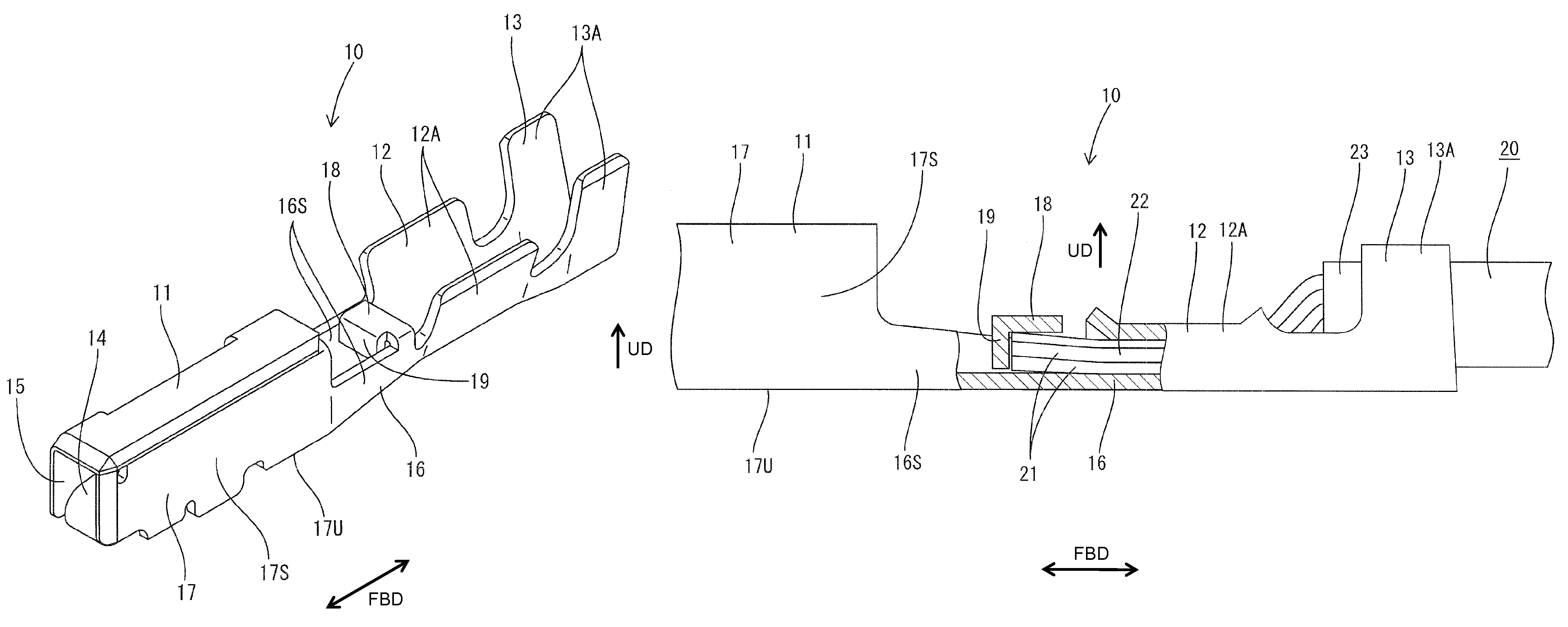
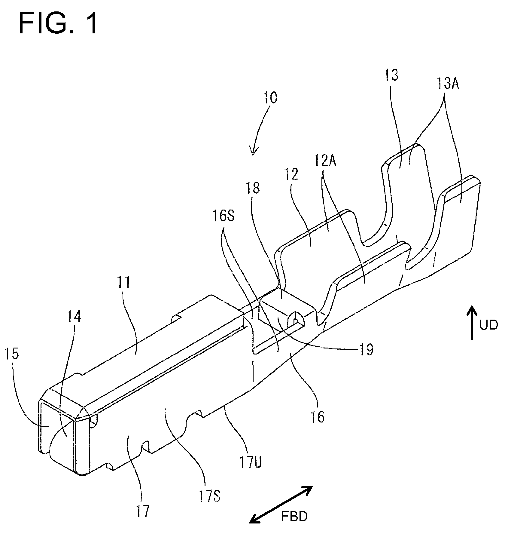
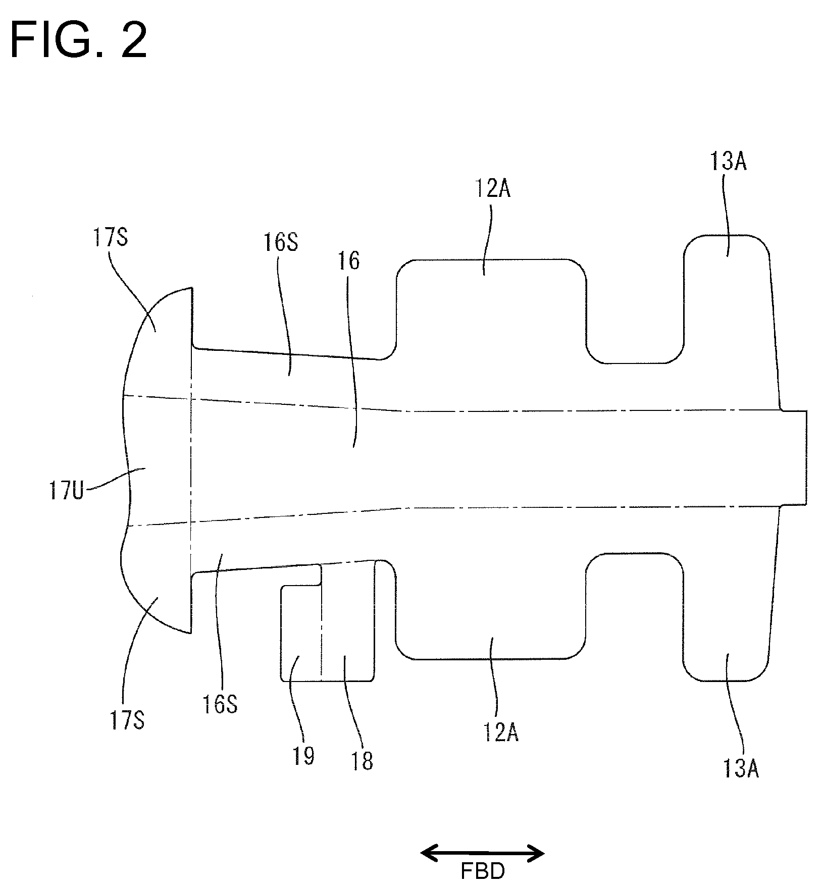
[0038]A female terminal fitting in accordance with the invention is identified by the numeral 10 in FIGS. 1 to 5. The terminal fitting 10 is formed by punching, stamping or cutting a substantially flat conductive metal plate out into a specified developed shape preferably by using a press forming machine. The cut or punched out metal plate then is bent, folded and / or embossed. The terminal fitting 10 includes a connecting portion 11 to be connected with a mating male terminal fitting (not shown), a wire barrel 12 and an insulation barrel 13 successively formed behind the connecting portion 11. In the following description, upper, lower, left-lower and right-upper sides of FIG. 1 are referred to as upper, lower, front and rear sides.

[0039]The connecting portion 11 is formed by bending into a substantially rectangular tube that is long in forward and backward directions FBD and includes a resilient contact piece 14 inside. A tab (not shown) of the mating male terminal fitting can be i...

third embodiment

[0072]The terminal fitting 140 of the third embodiment has a coupling 142 formed between a connecting portion 141 and a wire crimping portion 145. The coupling 142 has two laterally symmetrical restrictions 152 and two laterally symmetrical reinforcements 151. Two horizontal extensions 146 are formed at the standing ends of left and right walls 144 of the coupling 142 and extend in substantially parallel to a bottom plate 143. Two extensions 147 extend down from front ends of the horizontal extensions 146 toward the bottom plate 143 and are substantially parallel to the side walls 144. The facing surfaces of the downward extensions 147 are held laterally in close contact with each other. Bottom ends of the downward extensions 147 are bent toward the side walls 144 to form locking projections 148.

[0073]A locking hole 149 vertically penetrates the bottom plate 143 at a widthwise central position and is long in forward and backward directions FBD. Portions of the bottom plate 143 on op...

second embodiment

[0076]Restrictions 152 are defined at rear end regions of the horizontal extensions 146. The restrictions 152 project forward from the wire barrel, similar to the second embodiment, and are positioned to cover the conductor 111 of the wire 110 accommodated in the coupling 142 to prevent the conductor 111 from being widened.


PUM


Abstract

A terminal fitting (10, 120, 210, 230) has a connecting portion (11, 121, 211) to be connected with a mating terminal and a wire barrel (12, 126, 212) to be crimped into connection with an end portion of a wire (20, 110, 220). A restriction (18, 152, 218A, 231) is between the connecting portion (11, 121, 211) than the wire barrel (12, 126, 212) and faces a placing surface of a bottom plate (16, 123, 216) where the end portion of the wire (20, 110, 220) is to be placed for restricting an upward movement of the end portion of the wire (20, 110, 220).

Description

BACKGROUND OF THE INVENTION[0001]1. Field of the Invention[0002]The invention relates to a terminal fitting including a wire barrel to be crimped into connection with an end portion of a wire.[0003]2. Description of the Related Art[0004]Japanese Unexamined Patent Publication No. 2004-303526 discloses a terminal fitting with a connecting portion to be connected with a mating terminal. A wire barrel is disposed behind the connecting portion and is configured to be crimped into connection with an exposed core of an end portion of a wire. The wire barrel is crimped at a position where the leading end of the core projects forward, so that the entire wire barrel is crimped into connection with the core. Further reference is made to Japanese Unexamined Patent Publication No. 2005-222815.[0005]The leading end of a core that projects forward from the wire barrel tends to be widened and may bend up when a wire barrel is crimped into connection with an end portion of a wire. A retainer may be ...

Claims


Application Information

Patent Timeline
Patent Type & Authority Patents(United States)
IPC IPC(8): H01R4/10
CPCH01R4/185H01R43/16H01R13/11
Inventor TABATA, MASAAKITAKEDA, KAZUAKIADACHI, HIDEO
Owner SUMITOMO WIRING SYST LTD
Why Eureka
Try Eureka