Crimp terminal

a crimp terminal and open barrel technology, applied in the direction of electrical equipment, connections, connections effected by permanent deformation, etc., can solve the problem of not getting sufficient high contact conductivity, and achieve the effect of improving the contact conductivity between the terminal and the conductor

Active Publication Date: 2013-06-06
YAZAKI CORP
View PDF3 Cites 12 Cited by
  • Summary
  • Abstract
  • Description
  • Claims
  • Application Information

AI Technical Summary

Benefits of technology

[0027]With the configuration described above, a ratio of a minor axis to a major axis of each of the recesses is set at 1:1.7 to 2.3. For this reas...

Problems solved by technology

For this reason, sufficiently high contact con...

Method used


Image

  • Crimp terminal
  • Crimp terminal
  • Crimp terminal

Examples


second embodiment

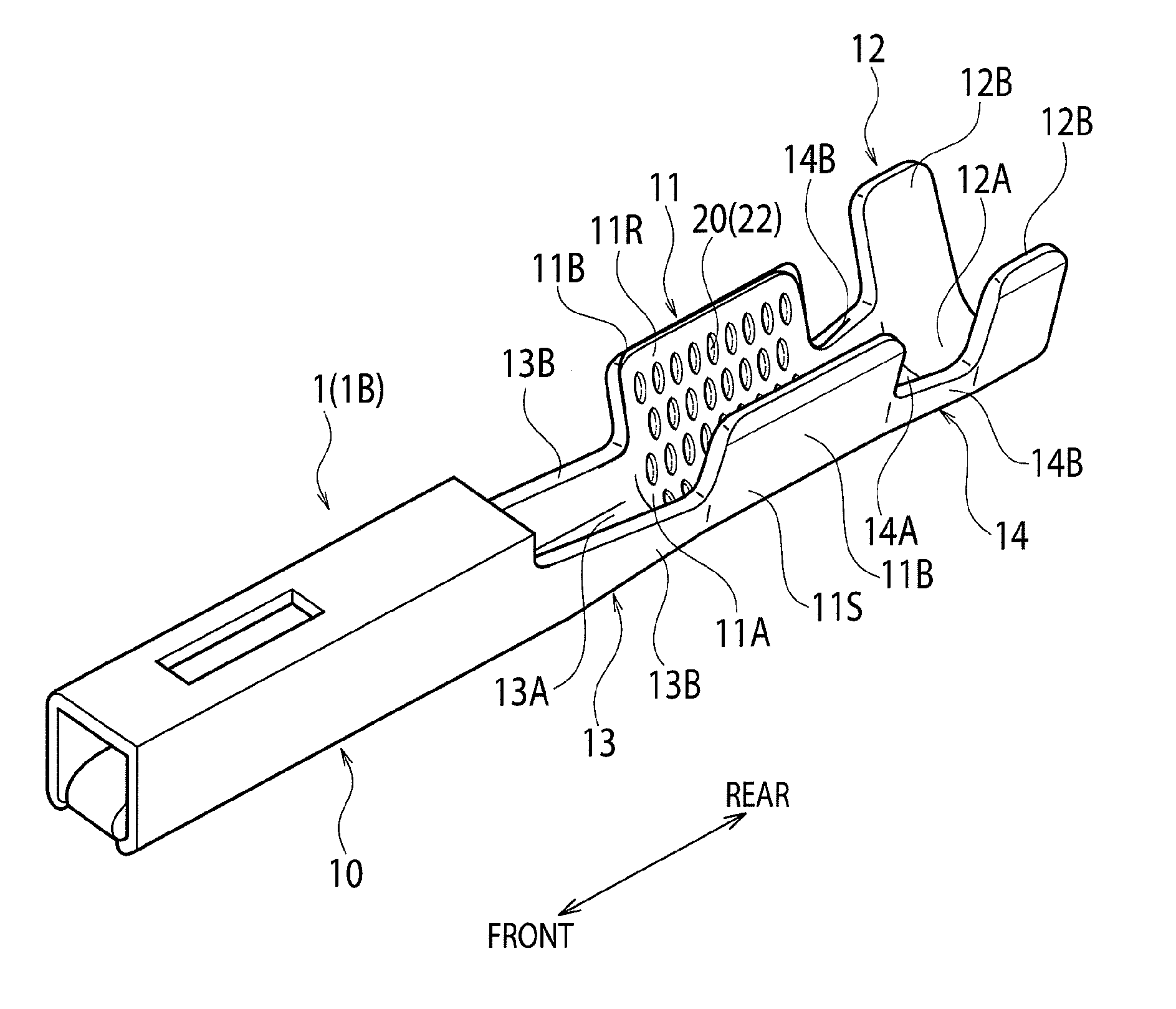
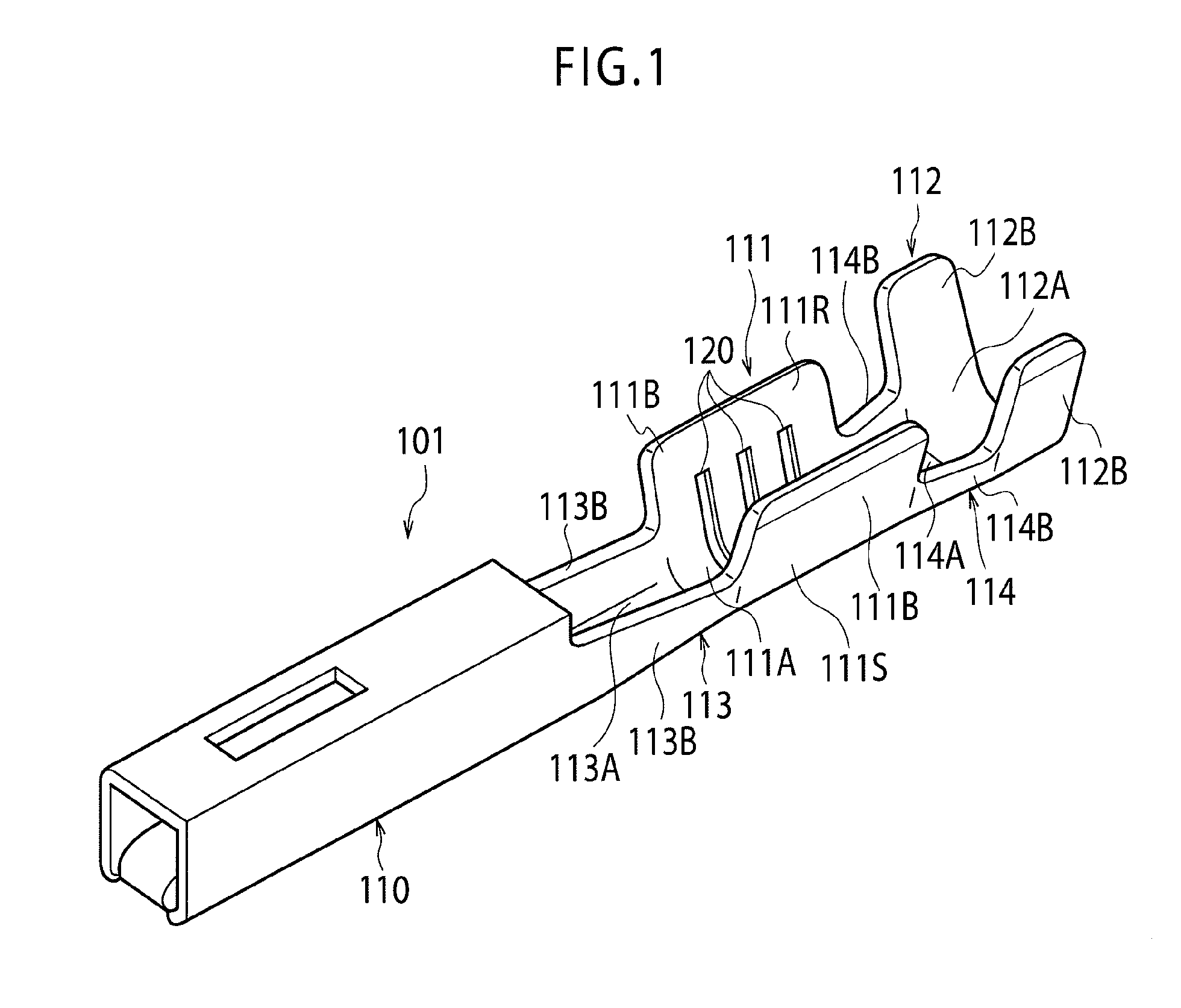
[0041]As shown in FIG. 6, each of crimp terminal 1, 1B according to a first or second embodiment is of a female type; includes a box-type electrical connection portion 10, which is to be connected to a male terminal of a mating connector, in a front portion in a longitudinal direction of the terminal (in which is also a longitudinal direction of a conductor of an electric wire to be connected thereto, i.e., a direction in which the electric wire extends); includes a conductor crimp portion 11, which is to be crimped around an exposed conductor Wa (see FIG. 11) of an end of an electric wire W, behind the electrical connection portion 10; and further includes a coated crimping portion 12, which is to be crimped around an insulation coating portion of the electric wire W, behind the conductor crimp portion 11. Each of the crimp terminal 1, 1B includes: a first joint portion 13, which joins the electrical connection portion 10 and the conductor crimp portion 11 together, between the ele...

first embodiment

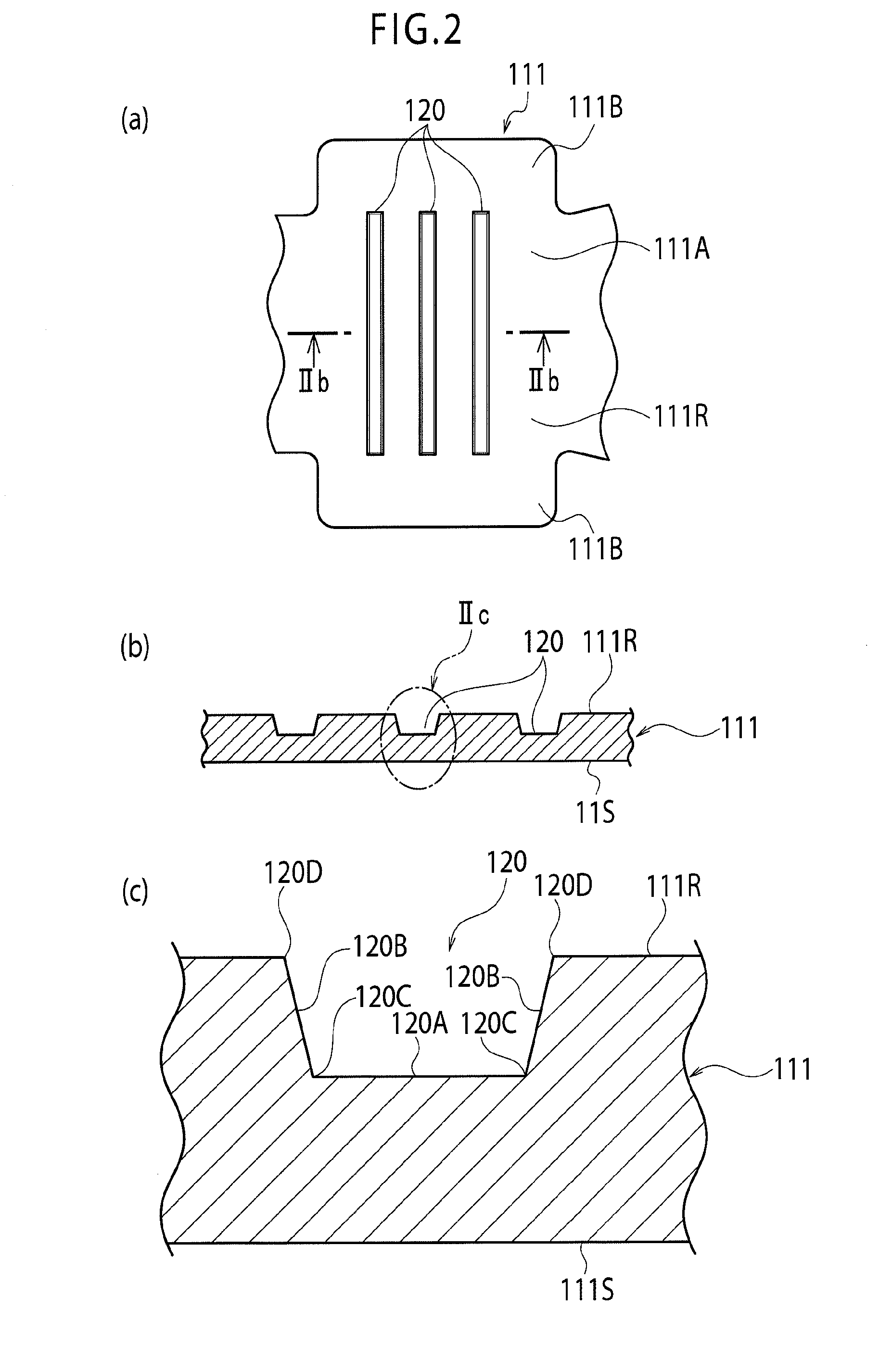
[0046]However, as shown in FIG. 7, in the crimp terminal 1 each recess 20 before crimping is formed in an elliptical shape (oval shape) in a posture where a minor axis direction of the recess 20 is oriented in a front-rear direction and a major axis direction thereof is oriented in a direction orthogonal to the front-rear direction, in order to take on a shape close to a perfect circle after crimping.

[0047]As shown in FIG. 8, in the crimp terminal 1B according to the second embodiment, each recess 22 before crimping is formed in an edge-rounded rectangular shape (oval shape) in a posture where a minor axis direction of the recess 22 is oriented in a front-rear direction and a major axis direction thereof is oriented in a direction orthogonal to the front-rear direction, in order to take on a shape close to a perfect circle after crimping.

[0048]In this case, a ratio of a minor axis to a major axis of each of the oval-shaped recesses 20, 22 is set at 1:1.7 to 2.3.

[0049]On the other h...


PUM


Abstract

A conductor crimp portion (11) includes, in an inner surface (11R) of the conductor crimp portion (11), circular recesses (20) as serrations of the conductor crimp portion (11) scattered to be spaced from each other. Each of the recesses (20) before crimping has an elliptical shape (oval shape) having a minor axis oriented in a front-rear direction and a major axis oriented in a direction orthogonal to the front-rear direction, to take on a shape close to a perfect circle after crimping.

Description

TECHNICAL FIELD [0001]The present invention relates to an open barrel type crimp terminal having a conductor crimp portion with a U-shaped cross section, which is used in an automotive electric system, for example.BACKGROUND ART [0002]FIG. 1 is a perspective view showing a configuration of a related crimp terminal described in Patent Document 1, for example.[0003]A crimp terminal 101 includes an electrical connection portion 110 which is to be connected to a terminal of a mating connector in its front portion in a longitudinal direction of the terminal (also in a longitudinal direction of a conductor of an electric wire which is to be connected thereto), includes a conductor crimp portion 111 which is to be crimped around an exposed conductor of an end of the electric wire (not illustrated) behind the electrical connection portion 110, and further includes a coated crimping portion 112 which is to be crimped around an insulation coating portion of the electric wire behind the conduc...

Claims


Application Information

Patent Timeline
IPC IPC(8): H01R4/18
CPCH01R4/188H01R4/185H01R4/18
Inventor ONUMA, MASANORITAKEMURA, KOUSUKE
Owner YAZAKI CORP
Why Eureka
Try Eureka