COG glass substrate structure and display panel

A technology for glass substrates and display panels, which is applied in the manufacture of instruments, electrical components, semiconductors/solid-state devices, etc. It can solve problems such as poor chip contact conductivity, cracks or incomplete cutting edges, and cracked metal pads.

Inactive Publication Date: 2019-05-24
WUHAN CHINA STAR OPTOELECTRONICS TECH CO LTD
View PDF8 Cites 0 Cited by
  • Summary
  • Abstract
  • Description
  • Claims
  • Application Information

AI Technical Summary

Problems solved by technology

When the glass substrate is cut, the cutting knife wheel needs a certain pressure, which will cause cracks or defects on the cutting edge of the glass substrate, so that the cracks or defects extend to the top of the glass substrate for a certain distance. distance, causing the metal pad to crack or damage, thereby affecting the performance of chip bonding, resulting in poor contact conductivity between the metal pad and the chip

Method used


Image

  • COG glass substrate structure and display panel
  • COG glass substrate structure and display panel
  • COG glass substrate structure and display panel

Examples


Embodiment Construction

[0021] In order to make the above and other objectives, features, and advantages of the present disclosure more comprehensible, preferred embodiments of the present disclosure will be exemplified below in detail with reference to the attached drawings. Furthermore, the direction terms mentioned in this disclosure, such as up, down, top, bottom, front, back, left, right, inside, outside, side layer, surrounding, center, horizontal, transverse, vertical, longitudinal, axial , radial direction, the uppermost layer or the lowermost layer, etc., are only directions for referring to the attached drawings. Therefore, the directional terms used are used to explain and understand the present disclosure, but not to limit the present disclosure.

[0022] In the figures, structurally similar units are denoted by the same reference numerals.

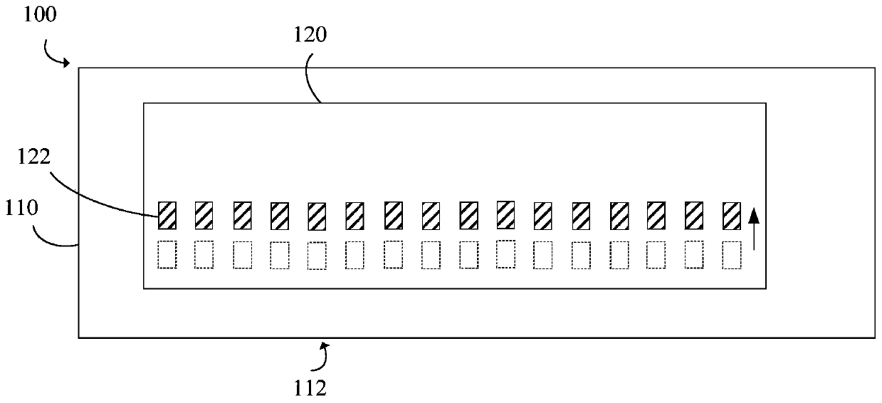
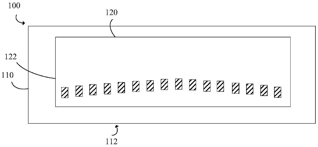
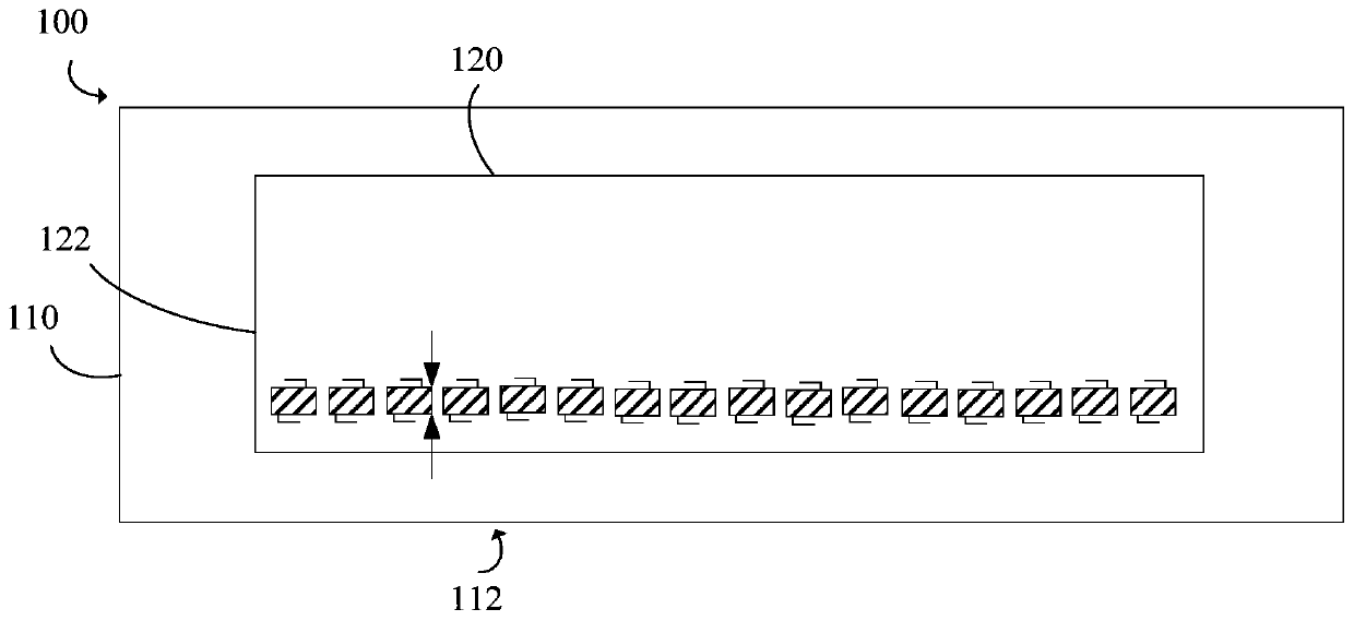
[0023] refer to Figure 1-3 , an embodiment of the present disclosure provides a COG glass substrate structure 100 . The COG glass substrate stru...


PUM


Abstract

The invention discloses a COG glass substrate structure and a display panel. The COG glass substrate structure comprises a glass substrate and a chip, the glass substrate comprises a cut edge, and thechip is fixed to the glass substrate and comprises a plurality of metal pads away from the cut edge of the glass substrate. Since the metal pads are arranged away from the cut edge of the glass substrate, damages of the metal pads due to cracks and incompleteness of the cut edge of the glass substrate can be reduced, and accordingly chip binding performances are improved, and contact conductivityof the metal pads and the chip is promoted.

Description

【Technical field】 [0001] The present disclosure relates to the field of display technology, in particular to a COG glass substrate structure and a display panel. 【Background technique】 [0002] In the current COG glass substrate structure, a plurality of metal pads of the chip are disposed adjacent to the cutting edge of the glass substrate. When the glass substrate is cut, the cutting knife wheel needs a certain pressure, which will cause cracks or defects on the cutting edge of the glass substrate, so that the cracks or defects extend to the top of the glass substrate for a certain distance. distance, causing the metal pad to be cracked or damaged, thereby affecting the performance of chip bonding, resulting in poor electrical conductivity between the metal pad and the chip. [0003] Therefore, it is necessary to provide a COG glass substrate structure and a display panel to solve the problems existing in the prior art. 【Content of invention】 [0004] To solve the abov...

Claims


Application Information

Patent Timeline
Patent Type & Authority Applications(China)
IPC IPC(8): G09F9/30
CPCG09F9/30H01L21/782
Inventor 卢延涛张鑫
Owner WUHAN CHINA STAR OPTOELECTRONICS TECH CO LTD
Why Eureka
Try Eureka