Flyline connecting device

a connecting device and flyline technology, applied in the direction of rod connection, coupling, manufacturing tools, etc., can solve the problems of not being most effectively or reliably connected to each other, difficult to re-insert the knot end of the flyline back into the link, and difficult to do without damaging the tensile bearing core, etc., to achieve the effect of reducing the inside diameter of the tubular lattice, wall section, and increasing tensile strength and toughness

Inactive Publication Date: 2012-07-03
KLEIN ARNOLD GREGORY
View PDF122 Cites 10 Cited by
  • Summary
  • Abstract
  • Description
  • Claims
  • Application Information

AI Technical Summary

Benefits of technology

[0007]It is the primary objective of the instant invention to provide an improved connector device for attaching the leader line or tippet to a fly fishing line. The key feature of this improved connecting device is the development of an elastically compressible tubular lattice that is of a unitary or unwoven structure. This flexible tubular lattice structure allows for a small, light and streamlined, in-line connection of the device to the fly-line. The manufacture of this tubular lattice feature is most easily achieved by the injection molding of an intermediate configuration having oversized dimensions. Once the intermediate configuration is injection molded, the device may be manually or machine “cold drawn” (stretched) to reduce the tubular lattice inside diameter, wall section and to greatly increase the tensile strength and toughness. The cold drawing operation, whether performed by the fisherman or completed at the end of the molding cycle, is facilitated by the incorporation of integrally molded stretching loops or other holding features. These stretching loops are clipped off the device by a secondary manufacturing operation or by the fisherman before the device is installed over the fly line. Installing the device is performed by distally compressing the tubular lattice and thereby expanding the inside diameter to allow for the progressive insertion of the fly line. Once the fly line is fully inserted, the fisherman releases the compressive force and the tubular lattice contracts down to constrict the fly line. It is important to note that the in the relaxed state (not compressed), the tubular lattice inside diameter is somewhat smaller than the fly line diameter so that it will elastically grip the fly line. The expandable tubular lattice tightens down and grips the fly line even more securely when a tension force is applied.
[0009]There are a number of different options and associated features for attaching the leader line or tippet to the connector device. The leader line or tippet may be tied directly or looped with an integrally formed loop or eyelet. Alternatively, the leader line or tippet may be affixed to the device using a very small knot-trapping feature. The leader line or tippet being typically much smaller in diameter than the fly line can be secured within the knot holding feature using a relatively small overhand knot. An advantage of using the knot holding feature over the loop or eyelet is that the connection between the lines is very small and streamlined and this connection maintains axial alignment and stiffness between the lines. The axially aligned connection does not pivot or hinge as loop connections tend to do, thus preserving the fly-casting energy and accuracy. This fly line connecting device has substantial advantages over the existing knots and connection devices by virtue of being very lightweight, streamlined (low air / water resistance), and axial stiffness or resistance to pivoting or hinging at the connection junction.

Problems solved by technology

These two lines, the fly-line and leader-line are designed with very different attributes and are not most effectively or reliably connected to each other using knots, even those developed specifically for this purpose.
In practice, it is often fairly difficult to re-insert the knot end of the fly line back into the link, due to the size interference between the fly line knot and the link slot.
It is often necessary to try and strip off some of the fly line surface coating before tying the knot in an attempt to reduce the overall knot size, but this is difficult to do without damaging the tensile bearing core.
There is sometimes the additional problem of tying the leader knot with a sufficient cross section to keep it from being pulled transversely through the link.
The practical necessity to tie an overhand knot in the fly line and a clinch knot in the leader and then to seat these knots within the very confined space of the link slot along with the relatively large link diameter (as compared to the fishing lines) has made this fly-line to leader link a less than desirable solution to a large number of fly fishing practitioners.
These braided loops are somewhat difficult to install as they must be progressively expanded and pulled (teased) over the terminal end of the fly line.
Unfortunately, installing these braided loops always results in the fraying of the braided tubular opening of the device.
Failure to cover this frayed end will typically result in the braided loop being pulled off the fly line.
The installation difficulties and performance drawbacks of the braided loops are actually more serious than the fly line to leader connector links as described above, but they remain very popular.
These specialized connecting lines have to be used exclusively with each other, and as a result are limiting to the flexibility of line and leader setup by the fisherman.
These specialized devices also tend to be larger in size than is desirable.
None of the prior art connection devices makes use of a light, flexible, compressively expandable tubular lattice structure to make a reliable, in-line, and very streamlined connection between the fly line and leader line.

Method used


Image

  • Flyline connecting device
  • Flyline connecting device
  • Flyline connecting device

Examples


Embodiment Construction

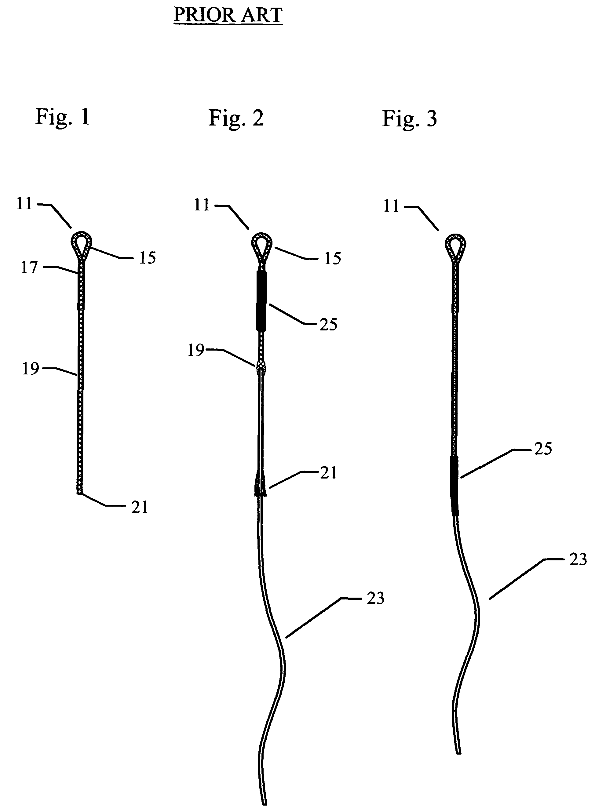
[0036]The prior art “braided loop” device 11 is shown in the FIGS. 1 through 3. The device 11 as shown in FIG. 1 is formed of a braided (nylon) tubular sleeve 19 with a hand formed loop at 15. The loop 15 is made by tucking the end of the braided sleeve back into a stretched region of the weave where it is secured by cementing approximately 1″ of overlapping length of the braided nylon as seen at 17. The braided tubular sleeve 19 has an open tubular end to receive the fly line at 21. The FIG. 2 shows the fly line 23 being pushed into the expanded woven sleeve 19. The braided sleeve 19 opens up to receive the fly-line 21 as it is locally compressed. In order to get the fly line 23 fully inserted into the braided loop sleeve 19 it is necessary to tease the line further and further up the braided sleeve. This procedure is somewhat tedious as both the fly line and braided loop are prone to flexing. The braided loop device 11 stays in place on the fly-line 23 by a mechanism similar to ho...


PUM


Abstract

The invention provides a convenient, lightweight and streamlined connecting device for attaching a leader or tippet to a fly-fishing line. The Fly Line Connecting Device is configured with an expandable tubular lattice that allows for an in-line connection to the fly line. The connection device has an integral tubular lattice sized with an internal diameter that is slightly smaller that the fly line and when compressively displaced, operates to expand the internal diameter to allow insertion of the fly line. Once the fly line is fully inserted, the tubular lattice is allowed to contract and elastically constrict onto and thereby grip the semi-resilient surface of the fly line. When the fly line and leader line are placed in tension through the connecting device, the tubular lattice acts to constrict down on the fly-line to resist separation. The connecting device of the invention is configured with a loop, eyelet, knot-trapping feature, or short tippet to allow for the convenient attachment of the leader line. Alternatively, the connecting device is permanently attached or integrally formed with a full-length leader. The preferred embodiment of the connecting device is injection molded in an intermediate form that is configured to be manually or machine cold-drawn to the final working dimensions and optimal physical properties.

Description

[0001]Applicant claims the benefit of provisional patent application No. 61 / 004,631 filed Nov. 30, 2007.FIELD OF THE INVENTION[0002]The instant invention is for a device to be used for the practice of fly-fishing. The device is used to connect the fly line to the leader line or tippet.BACKGROUND OF THE INVENTION[0003]The practice of fly-fishing typically requires the fisherman to make some sort of tension resisting connection between the weighted fly line (normally tapered, and coated with a semi-resilient polymer) and a leader line (clear or slightly tinted) to which the artificial fly, nymph or other fish attracting lure is terminally attached. These two lines, the fly-line and leader-line are designed with very different attributes and are not most effectively or reliably connected to each other using knots, even those developed specifically for this purpose.[0004]This fly line to leader connection problem is addressed by a number of prior art devices, all of which have inherent ...

Claims


Application Information

Patent Timeline
Patent Type & Authority Patents(United States)
IPC IPC(8): A01K91/12A01K91/047
CPCA01K91/047A01K91/12Y10T24/39Y10T403/18Y10T24/3913Y10T403/5706Y10T24/3998
Inventor KLEIN, ARNOLD GREGORY
Owner KLEIN ARNOLD GREGORY
Why Eureka
Try Eureka