Downhole gas detection in drilling muds

a technology of drilling mud and gas detection, which is applied in the direction of surveying, borehole/well accessories, instruments, etc., can solve the problems of equipment damage, downhole tools damaged, damage to the well,

Active Publication Date: 2010-10-19
BAKER HUGHES INC
View PDF19 Cites 24 Cited by
  • Summary
  • Abstract
  • Description
  • Claims
  • Application Information

AI Technical Summary

Problems solved by technology

Some fluids entering the borehole may cause corrosion to downhole tools.
Such “kicks” can cause equipment damage, damage to the well, environmental concerns, and pose serious safety hazards for personnel at the well site.
Kick may also be the result of washout due to unstable formations.
In other cases, gases produced from formations quickly reduce return fluid density.

Method used


Image

  • Downhole gas detection in drilling muds
  • Downhole gas detection in drilling muds
  • Downhole gas detection in drilling muds

Examples


Embodiment Construction

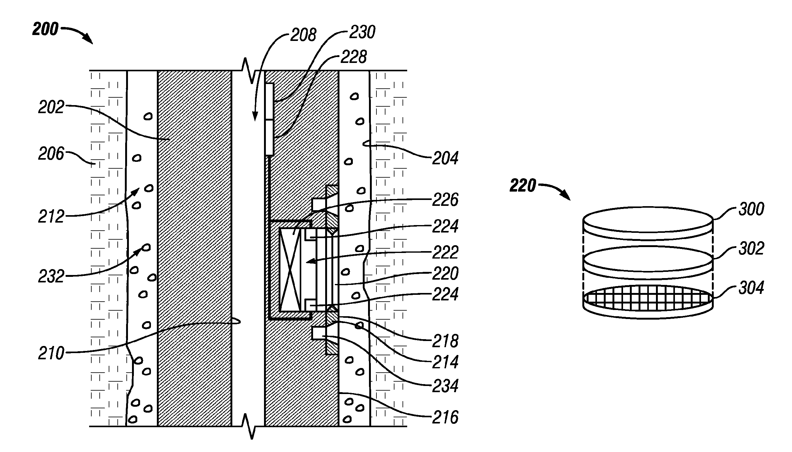
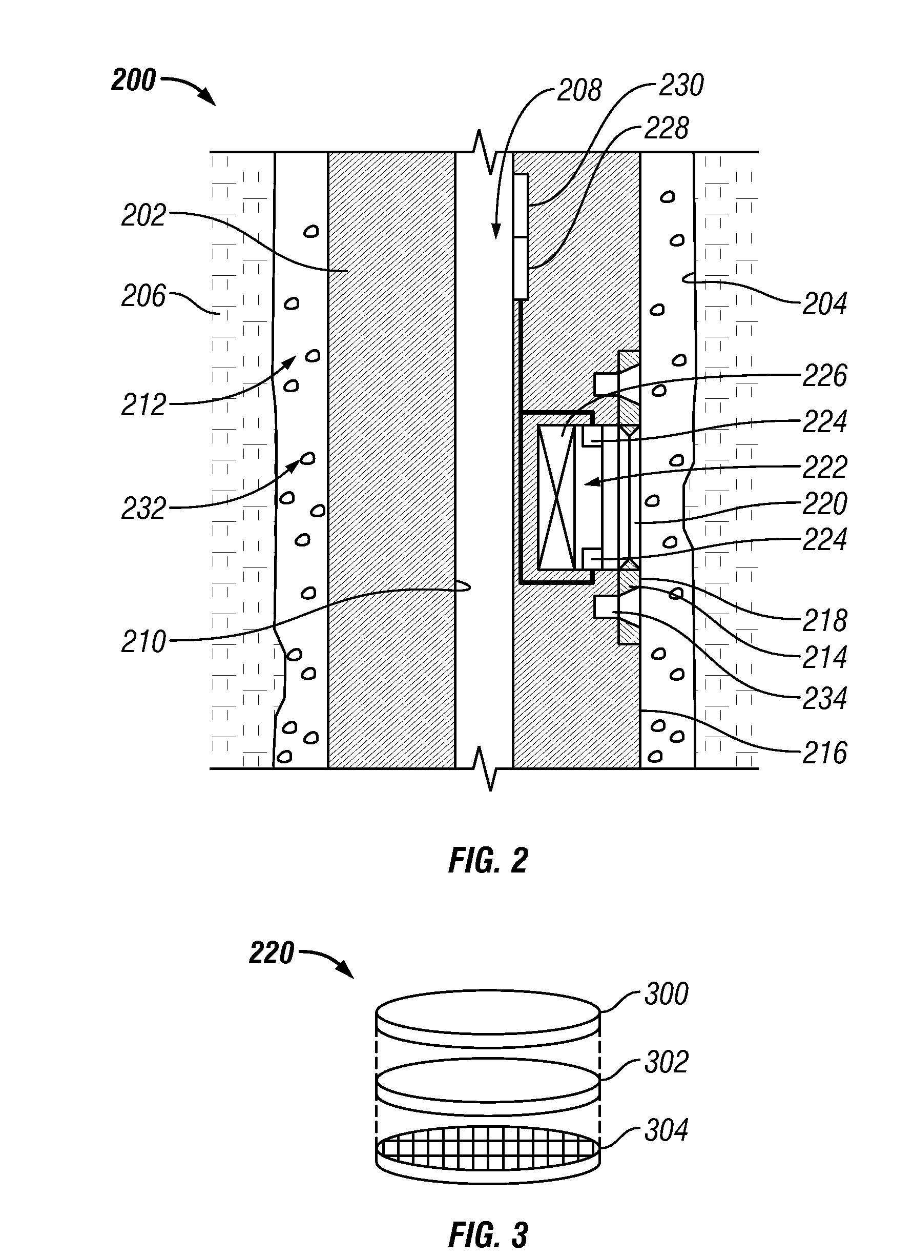
[0016]The present disclosure uses terms, the meaning of which terms will aid in providing an understanding of the discussion herein. Drilling fluid refers to fluid pumped primarily through a drill string toward a drill bit, and “return fluid” refers to annular fluid returning toward the surface of a well borehole. Return fluid will typically include drilling fluid contaminated by cuttings generated by a drill bit and by formation pore fluids. For the purpose of this disclosure, the term “kick” means any unscheduled entry of formation fluid into the borehole. The term “semi-permeable” used herein means substantially permeable by a gas or vapor and substantially impermeable by liquids and particulates.

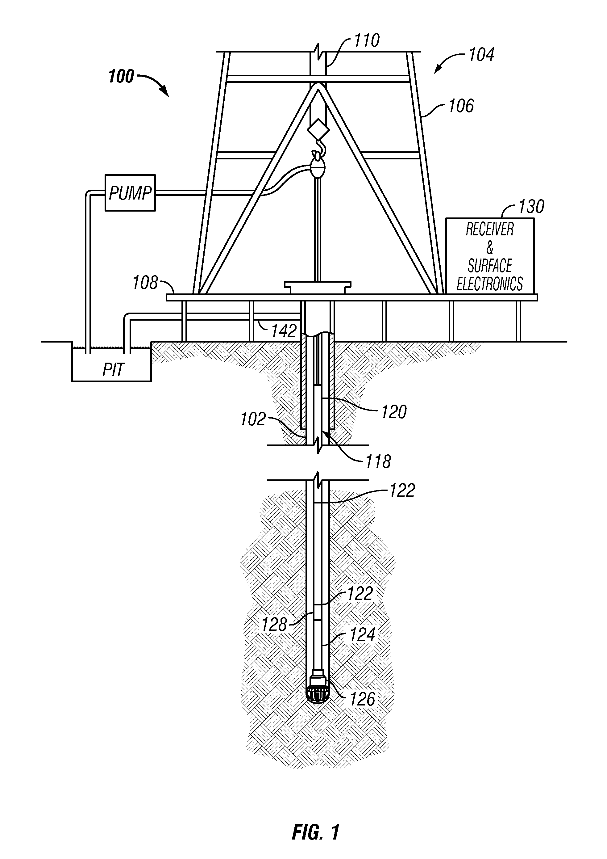
[0017]FIG. 1 shows an elevation view of a non-limiting exemplary simultaneous drilling and logging system 100 that may be used in several embodiments of the present disclosure. A well borehole 102 is shown drilled into the earth under control of surface equipment including a drilling rig...


PUM


Abstract

Apparatus and method are disclosed for detecting gas in return fluids. A semi-permeable interface is disposed on a tool sub, the semi-permeable interface being in communication with a fluid cell and with a return fluid in an annular region defined by an outside the tool sub and a borehole wall. A sensor responsive to a gas carried by the return fluid is disposed in the fluid cell to sense the gas that enters the fluid cell from the return fluid via the semi-permeable interface.

Description

BACKGROUND[0001]1. Technical Field[0002]The present disclosure generally relates to well bore tools and in particular to apparatus and methods for conducting downhole operations.[0003]2. Background Information[0004]Oilfield wellbores are formed by rotating a drill bit carried at an end of a drill string. A typical drill string includes a tubing, which may be drill pipe made of jointed sections or a continuous coiled tubing, and a drilling assembly that has a drill bit at its bottom end. The drill bit is rotated by a mud motor carried by a drilling assembly carried on the drill string and / or by rotating the drill pipe. Drilling fluid, also referred to as the “mud,” is pumped under pressure through the tubing from a source called a mud pit located at the surface. The drilling fluid exits the tubing through a drill bit and returns to the surface by flowing upward in an annulus between the tubing and the borehole wall. The drilling fluid is usually a combination of solids, water and var...

Claims


Application Information

Patent Timeline
Patent Type & Authority Patents(United States)
IPC IPC(8): E21B47/00
CPCE21B47/10G01N33/2823E21B49/081
Inventor DIFOGGIO, ROCCO
Owner BAKER HUGHES INC
Why Eureka
Try Eureka