Drilling system and method

a drilling system and drilling method technology, applied in the direction of chemistry apparatus and processes, wellbore/well accessories, construction, etc., can solve the problems of reducing the pressure of the bottomhole below the reservoir fluid pressure, overcoming the fracture strength of the rock, and affecting the operation of the well

Inactive Publication Date: 2003-05-01
SECURE DRILLING INT
View PDF19 Cites 149 Cited by
  • Summary
  • Abstract
  • Description
  • Claims
  • Application Information

AI Technical Summary

Benefits of technology

[0038] Thus, the open literature is extremely rich in pointing out methods for detecting kicks, and then methods for circulating kicks out of the wellbore. Generally all references teach methods that operate under conventional drilling conditions, that is, with the well being open to the atmosphere. However, there is no suggestion nor description of a modified drilling method and system, which, by operating with the well closed, controlling the flow rates in and out of the wellbore, and adjusting the pressure inside the wellbore as required, causing that influxes (kicks) and fluid losses do not occur or are extremely minimized, such method and system being described and claimed in the present application. In a particular advantage of the present invention the system and method differ from UBD methods which operate with closed well but generate a constant controlled influx of fluid, as hereinbefore described. Moreover the system and method are adapted for operation with a substantially incompressible drilling fluid whereby changes in pressure / flow may be detected or made at the wellhead and the effect downhole may be accurately calculated without complex pressure differential considerations. Nevertheless for offshore drilling, the present method and system employing back pressures can also be used with lightweight fluids so that the equivalent drilling fluid weight above the mud line can be set lower than the equivalent fluid weight inside the wellbore, with increasing safety and low cost relative to drilling with conventional fluids.
[0039] In its broadest aspect the present invention is directed to a system for operating a well having a drilling fluid circulating therethrough comprising means for monitoring the flow rates in and out and means to predict a calculated value of flow out at any given time to obtain real time information on discrepancy between predicted and monitored flow out, thereby producing an early detection of influx or loss of drilling fluid, the well being closed with a pressure containment device at all times.
[0040] The pressure / containment device may be a rotating blow out preventer (BOP) or a rotating control head, but is not limited to it. The location of the device is not critical. It may be located at the surface or at some point further down e.g. on the sea floor, inside the wellbore, or at any other suitable location. The type and design of device is not critical and depends on each well being drilled. It may be standard equipment that is commercially available or readily adapted from existing designs.
[0041] The function of the rotating pressure containment device is to allow the drill string to pass through it and rotate, if a rotating drilling activity is carried on, with the device closed, thereby creating a back pressure in the well. Thus, the drill string is stripped through the rotating pressure containment device which closes the annulus between the outside of the drill pipe and the inside of the wellbore / casing / riser. A simplified pressure containment device may be a BOP designed to allow continuous passage of non-jointed pipe such as the stripper(s) on coiled tubing operations.
[0042] The well preferably comprises a pressure containment device which is closed at all times, and a reserve BOP which can be closed as a safety measure in case of any uncontrolled event occurring.
[0043] Reference herein to a well is to an oil, gas or geothermal well which may be onshore, offshore, deepwater or ultra-deepwater or the like. Reference herein to circulating drilling fluid is to what is commonly termed the mud circuit, the circulation of the drilling fluid down the wellbore may be through a drill string and the return through an annulus, as in prior art methods, but not limited to it. As a matter of fact, any way of circulation of the drilling fluid may be successfully employed in the practice of the present system and method, no matter where the fluids are injected or returned.

Problems solved by technology

However, in many situations, it can happen that the bottomhole pressure is reduced below the reservoir fluid pressure.
However, if, by any means, the detection of such a kick takes a long time, the situation can become out of control leading to a blowout.
On the other hand, if the wellbore pressure is excessively high, it overcomes the fracture strength of the rock.
In this case loss of drilling fluid to the formation is observed, causing potential danger due to the reduction in hydrostatic head inside the wellbore.
This reduction can lead to a subsequent kick.
This induced well pressure, which by default, is greater than the reservoir pressure causes a lot of damage, i.e., reduction of near wellbore permeability, through fluid loss to the formation, reducing the productivity of the reservoir in the majority of cases.
This procedure takes time and increases the risk of blow-out, if the rig crew does not quickly suspect and react to the occurrence of a kick.
Procedure to shut-in the well can fail at some point, and the kick can be suddenly out of control.
In addition to the time spent to control the kicks and to adjust drilling parameters, the risk of a blow-out is significant when drilling conventionally, with the well open to the atmosphere at all times.
This method does not detect liquid (water or oil) kicks.
However, annular pressure data recorded during kill operations have also revealed that conventional killing procedures do not always succeed in keeping the bottomhole pressure constant.
That is, literature methods are directed to the detection and correction of a problem (the kick), while there are no known methods directed to eliminating said problem, by changing or improving the conventional method of drilling wells.
This technique implies a concomitant production of the reservoir fluids while drilling the well.
In many situations, however, it will not be possible to drill a well in the underbalanced mode, e.g., in regions where to keep the wellbore walls stable a high pressure inside the wellbore is needed.
In this case, if the wellbore pressure is reduced to low levels to allow production of fluids the wall collapses and drilling cannot proceed.
Also, wells are now drilled in areas with increasing environmental and technical risks.
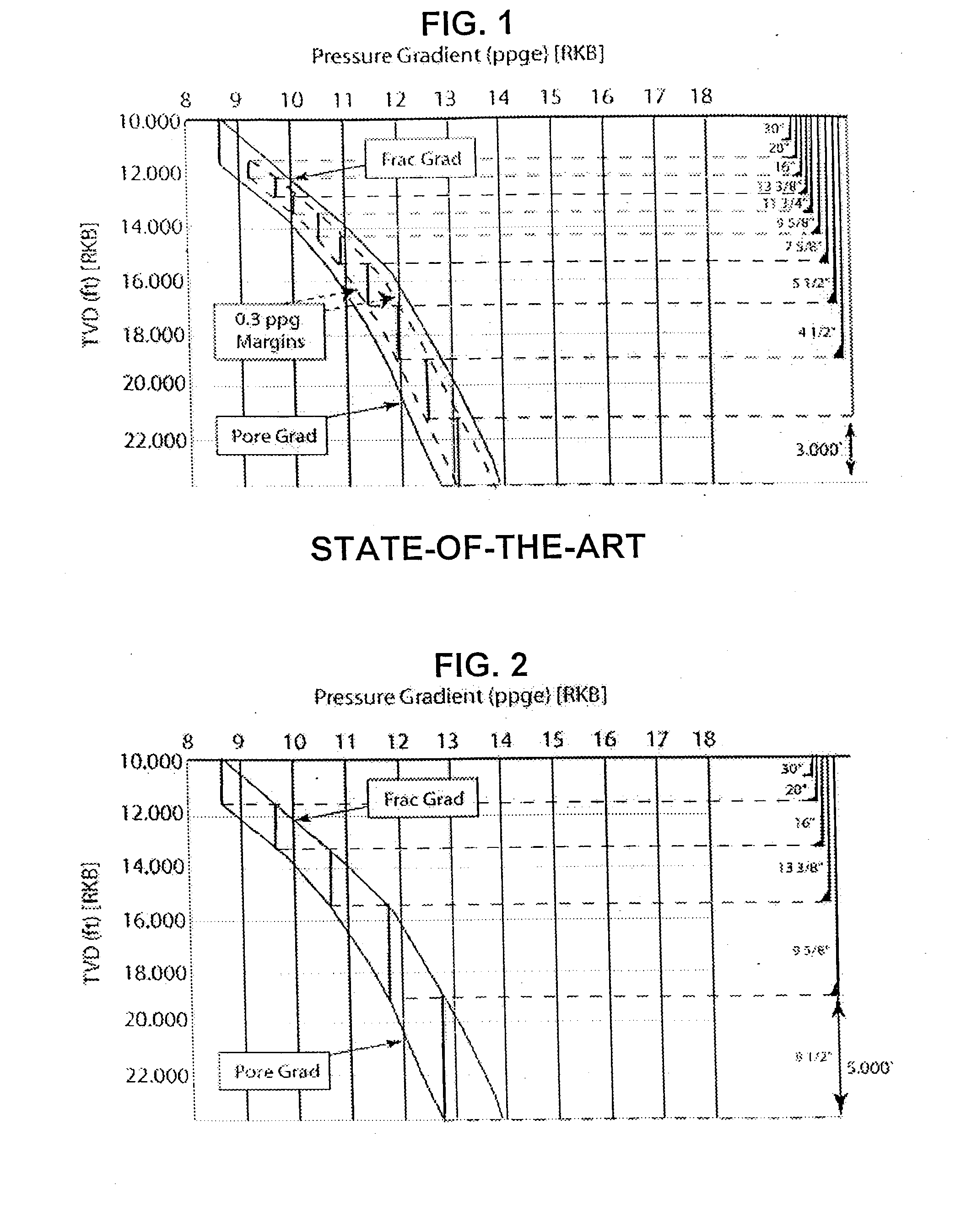
In this context, one of the big problems today, in many locations, is the narrow margin between the pore pressure (pressure of the fluids--water, gas, or oil--inside the pores of the rock) and the fracture pressure of the formation (pressure that causes the rock to fracture).
In this situation, a reduction in bottomhole pressure, caused by the upward movement of the drill string can lead to an influx.
From FIG. 1, it can be seen that the last phase of the well can only have a maximum length of 3,000 ft, since the mud weight at this point starts to fracture the rock, causing mud losses.
It is not difficult to imagine the problems created by drilling in a narrow margin, with the requirement of several casing strings, increasing tremendously the cost of the well.
Moreover, the current well design shown in FIG. 1 does not allow to reach the total depth required, since the bit size is continuously reduced to install the several casing strings needed.
In most of these wells, drilling is interrupted to check if the well is flowing, and frequent mud losses are also encountered.
In many cases wells need to be abandoned, leaving the operators with huge losses.
These problems are further compounded and complicated by the density variations caused by temperature changes along the wellbore, especially in deepwater wells.
This can lead to significant problems, relative to the narrow margin, when wells are shut in to detect kicks / fluid losses.
The cooling effect and subsequent density changes can modify the ECD due to the temperature effect on mud viscosity, and due to the density increase leading to further complications on resuming circulation.
Thus using the conventional method for wells in ultra deep water is rapidly reaching technical limits.
The industry has mainly taken the direction of the second alternative, due to arguments that well control and understanding of two-phase flow complicates the whole drilling operation with gas injection.
However, there are several technical issues to be overcome with this option, which will delay field application for some years.
The cost of such systems is also another negative aspect.
Potential problems with subsea equipment will make any repair or problem turn into a long down-time for the rig, increasing even further the cost of exploration.
This alternative is much simpler than the expensive mud lift methods, but there are still some problems and limitations, such as the separation of the spheres from the liquid coming up the riser, so that they can be injected again at the bottom of the ocean.
This requirement stems from the fact that an emergency disconnection might happen, and all of a sudden, the hydrostatic column provided by the mud inside the marine riser is abruptly lost.
If the weight of the fluid remaining inside the well after the disconnection of the riser is not high enough to balance the pore pressure of the exposed formations, a blowout might occur.
This safety guard is called Riser Margin, and currently there are several wells being drilled without this Riser Margin, since there is no dual-density method commercially available so far.
These methods have limited application, i.e., underbalanced and air drilling are limited to formations with stable wellbores, and there are significant equipment and procedural limitations in handling produced effluent from the wellbore.
The underbalanced method is used for limited sections of the wellbore, typically the reservoir section.
This limited application makes it a specialist alternative to conventional drilling under the right conditions and design criteria.
Air drilling is limited to dry formations due to its limited capability to handle fluid influxes.
Similarly Mud-Cap drilling is limited to specific reservoir sections (typically highly fractured vugular carbonates).
When the liquid phase is oil, the oil can be diesel, synthetic, mineral, or vegetable oil, the advantage being the reduced density of oil compared to water, and the disadvantage being the strong negative effect on the environment.
In some cases measurement of the flow rate only is not accurate enough to provide a clear indication of losses or gains while drilling.
This is in contrast to known open well systems which require pausing fluid injection and drilling to unload excess fluid, and add additional fluid, by trial and error until pressure is restored, which can take a matter of hours of fluid circulation to restore levels.
The speed of adjustment is much greater in the present method, as opposed to the conventional situation, where increasing the mud density (weighting up) or decreasing the mud density (cutting back) is a very time consuming process.
In these cases, it is common to observe influxes when circulation is interrupted, increasing substantially the risks of drilling with the conventional drilling system.
This leads to significant time savings as the traditional approach to dealing with influxes is very time-consuming: stopping drilling, shutting in the well, observing, measuring pressures, circulating out the influx by the accepted methods, and adjusting the mud weight.
Similarly a loss of drilling fluid to the formation leads to analogous series of time-consuming events.
In these cases, if a conventional drilling fluid is used, the initial bottomhole pressure might be already high enough to fracture the formation and cause mud losses.
On the other hand, if the fluid volume returning is decreasing, after compensating for all possible factors it means the pressure inside the wellbore is higher than the fracture pressure of the rock, or that the sealing of the drilling mud is not effective.
However, the current technical limit on some ultra-deep water wells, due to the narrow margin, when drilling with the prior art method, leads to a sequence of fluid influxes / losses due to the inaccuracies in manually controlling the mud density and subsequent ECD as described above, that can lead to loss of control of the drilling situation and has resulted in the abandonment of such wells due to the safety risks and technical inability to recover from the situation.
At this point no more gas will enter the well and the problem is limited to circulating out the small amount of gas that might have entered the well.

Method used


Image

  • Drilling system and method
  • Drilling system and method
  • Drilling system and method

Examples


example 1

Identifying and Controlling Influx or Fluid Loss

[0258] Usually, in the prior art methods and systems indirect estimation made before drilling, based on correlations from logs, or during drilling using drilling parameters are the best alternatives to determine the pore pressure. Similarly, fracture pressure is also indirectly estimated from logs before drilling. In some situations the fracture pressure is determined at certain points while drilling, usually when a casing shoe is set, not along the whole well.

[0259] Advantageously, when using the method and system of the invention the pore and fracture pressure may be directly determined while drilling the well. This entails great savings as regards safety and time, two parameters of utmost importance in drilling operations.

[0260] In prior art methods, the bottomhole pressure is adjusted by increasing or reducing the mud weight. The increase or reduction in mud weight is most of the time effected based on quasi-empirical methods, whic...

example 2

Comparison with Conventional Methods

[0268] It has been mentioned before that in the conventional drilling methods the hydrostatic pressure exerted by the mud column is responsible for keeping the reservoir fluids from flowing into the well. This is called a primary safety barrier. All drilling operations should have two safety barriers, the second one usually being the blow-out preventer equipment, which can be closed in case an influx occurs. The drilling method and system herein described introduces for the first time three safety barriers during drilling, these being the drilling fluid, the blow-out preventer equipment, and the rotating pressure containment device.

[0269] In underbalanced drilling (UBD) operations, there are just two barriers, the rotating pressure containment device and the blow-out preventer, since the drilling fluid inside the wellbore must exert a bottomhole pressure smaller than the reservoir pressure to allow production while drilling.

[0270] As noted before,...

example 3

Design of modules

[0295] For a well determining number and location of pressure / flow control devices (chokes) required and required operating pressure range. Skid comprising eg 3 parallel injection lines each having sensors, and a common degasser is designed for eg 5000 psi in 3 chokes, or greater pressure tolerance in 10 chokes etc. Skid can be simply installed in any conventional system. A further skid may comprise one or more chokes with a bypass for adjustment. A further skid may comprise a dedicated circulating system for injection direct into the annulus


PUM


Abstract

A closed-loop circulating system for drilling wells has control of the flow rates in and out of the wellbore. Kicks and fluid losses are quickly controlled by adjusting the backpressure. Kick tolerance and tripping margins are eliminated by real-time determination of pore and fracture pressure. The system can incorporate a rotating BOP and can be used with underbalanced drilling.

Description

[0001] The present invention deals with a closed-loop system for drilling wells where a series of equipment, for the monitoring of the flow rates in and out of the well, as well as for adjusting the back pressure, allows the regulation of the out flow so that the out flow is constantly adjusted to the expected value at all times. A pressure containment device keeps the well closed at all times. Since this provides a much safer operation, its application for exploratory wells will greatly reduce the risk of blow-outs. In environments with narrow margin between the pore and fracture pressure, it will create a step change compared to conventional drilling practice. In this context, applications in deep and ultra-deep water are included. A method for drilling, using said system, is also disclosed. The drilling system and method are suited for all types of wells, onshore and offshore, using a conventional drilling fluid or a lightweight drilling fluid, more particularly a substantially i...

Claims


Application Information

Patent Timeline
Patent Type & Authority Applications(United States)
IPC IPC(8): E21B21/00E21B21/08E21B44/00
CPCE21B21/08E21B2021/006E21B44/00E21B21/085
Inventor LEUCHTENBERG, CHRISTIAN
Owner SECURE DRILLING INT
Why Eureka
Try Eureka