Continuous flow drilling systems and methods

Active Publication Date: 2009-01-29
WEATHERFORD TECH HLDG LLC
View PDF48 Cites 146 Cited by
  • Summary
  • Abstract
  • Description
  • Claims
  • Application Information

AI Technical Summary

Benefits of technology

[0015]In another embodiment, a method for drilling a wellbore includes injecting drilling fluid into a top of a tubular string disposed in the wellbore at a first flow rate. The tubular string includes: a drill bit disposed on a bottom thereof, tubular joints connected together, a longitudinal bore therethrough, and a port through a wall thereof. The drilling fluid exits the drill bit and carries cuttings from the drill bit. The cuttings and drilling fluid (returns) flow to the surface via an annulus defined between the tubular string and the wellbore. The method further includes engaging the tubular string with a rotating

Problems solved by technology

Interruption of drilling may mean that the circulation of the mud stops and has to be re-started when drilling resumes.
This can be time consuming, can cause deleterious effects on the walls of the wellbore being drilled, and can lead to formation damage and problems in maintaining an open wellbore.
The weighting of the mud can be very expensive.
This is inhibited by using relatively viscous drilling fluid; but thicker fluids require more power to pump.
Further, restarting fluid circulation following a cessation of circulation may result in the overpressuring of a formation in which the wellbore is being formed.

Method used


Image

  • Continuous flow drilling systems and methods
  • Continuous flow drilling systems and methods
  • Continuous flow drilling systems and methods

Examples


Embodiment Construction

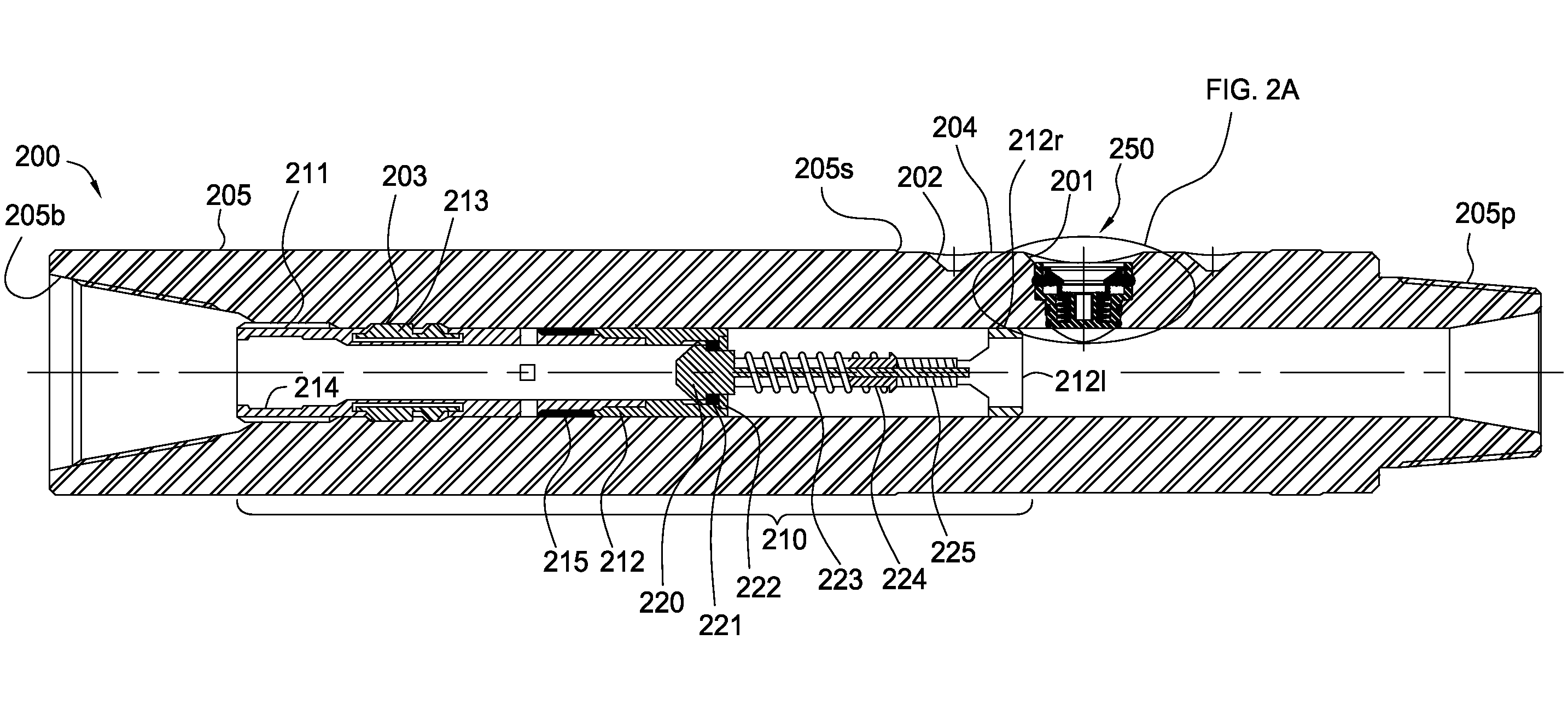
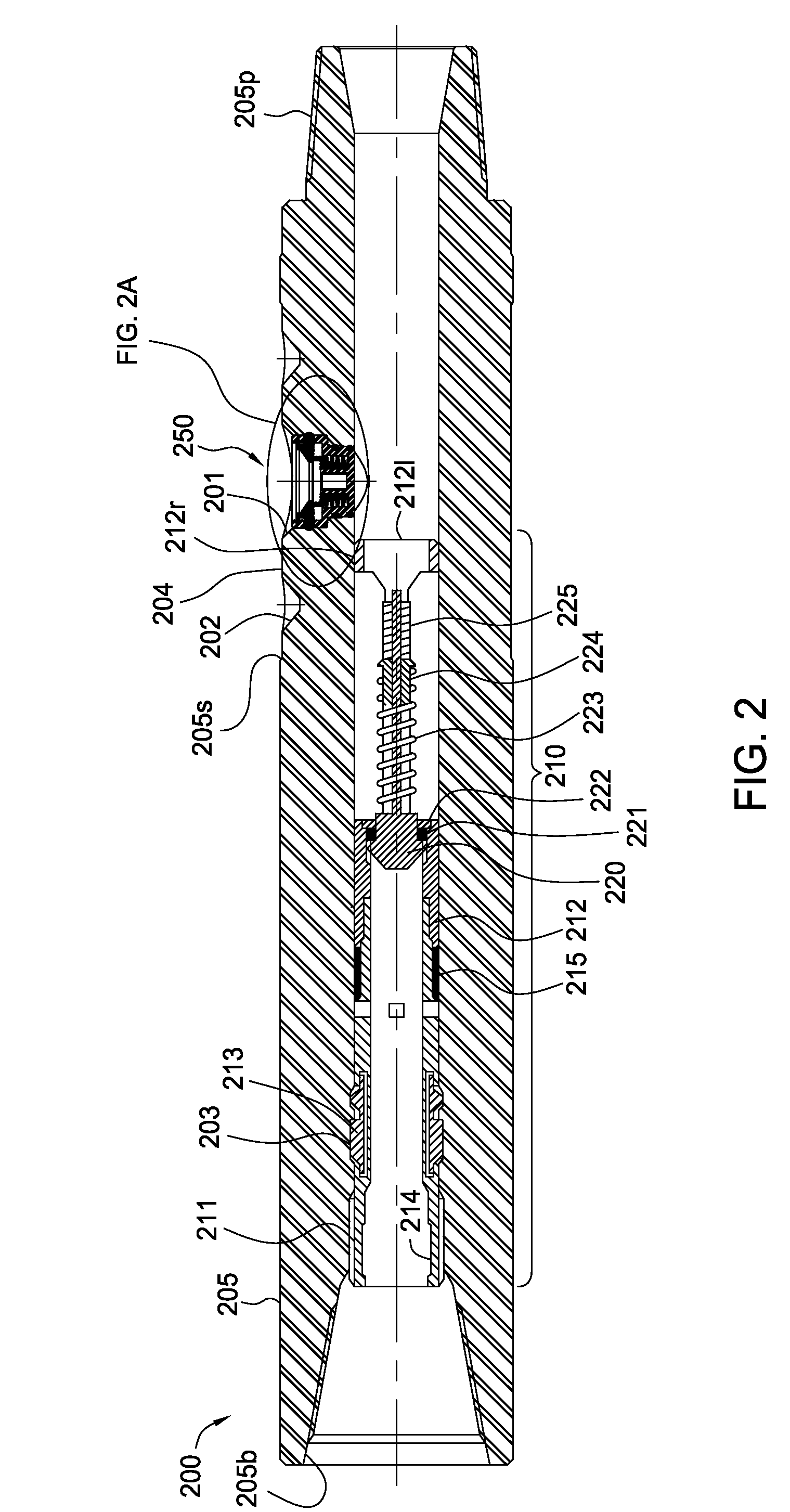
[0036]FIG. 2 is a cross-sectional view of a continuous flow sub (CFS) 200, according to one embodiment of the present invention. The CFS 200 may include a tubular housing 205, a float valve 210, and the plug 250. The tubular housing 205 may have a longitudinal bore therethrough, and a radial port 201 formed through a wall thereof in fluid communication with the bore. The housing 205 may also have a threaded coupling at each longitudinal end, such as box 205b formed in a first longitudinal end and a threaded pin 205p formed on a second longitudinal end, so that the housing may be assembled as part of the drill string 8. An outer surface of the housing 205 may taper at 205s from a greater diameter to a lesser diameter. The outer surface may then taper again and return to the greater diameter, thereby forming a recessed portion between the two tapers. The recessed portion may include one or more locator openings 202 formed therein, a seal face 204, and the port 201. A latch profile 203...


PUM


Abstract

In one embodiment, a method for drilling a wellbore includes injecting drilling fluid into a top of a tubular string disposed in the wellbore at a first flow rate. The tubular string includes: a drill bit disposed on a bottom thereof, tubular joints connected together, a longitudinal bore therethrough, and a port through a wall thereof. The drilling fluid exits the drill bit and carries cuttings from the drill bit. The cuttings and drilling fluid (returns) flow to the surface via an annulus defined between the tubular string and the wellbore. The method further includes rotating the drill bit while injecting the drilling fluid; remotely removing a plug from the port, thereby opening the port; and injecting drilling fluid into the port at a second flow rate while adding a tubular joint or stand of joints to the tubular string. The injection of drilling fluid into the tubular string is continuously maintained between drilling and adding the joint or stand to the drill string. The method further includes remotely installing a plug into the port, thereby closing the port. The first and second flow rates may be substantially equal or different.

Description

CROSS-REFERENCE TO RELATED APPLICATIONS[0001]This application claims the benefit of U.S. Prov. Pat. App. No. 60 / 952,539 (Atty. Dock. No. WEAT / 0836L), filed on Jul. 27, 2007, and U.S. Prov. Pat. App. No. 60 / 973,434 (Atty. Dock. No. WEAT / 0843L), filed on Sep. 18, 2007, which are herein incorporated by reference in their entireties.BACKGROUND OF THE INVENTION[0002]1. Field of the Invention[0003]The present invention relates to continuous flow drilling systems and methods.[0004]2. Description of the Related Art[0005]In many drilling operations in drilling in the earth to recover hydrocarbons, a drill string made by assembling pieces or joints of drill tubulars or pipe with threaded connections and having a drill bit at the bottom is rotated to move the drill bit. Typically drilling fluid, such as oil or water based mud, is circulated to and through the drill bit to lubricate and cool the bit and to facilitate the removal of cuttings from the wellbore that is being formed. The drilling f...

Claims


Application Information

Patent Timeline
IPC IPC(8): E21B7/00E21B33/00E21B34/00
CPCE21B19/16E21B21/10E21B21/002E21B21/12E21B2034/005E21B21/106E21B2200/05
Inventor IBLINGS, DAVIDBAILEY, THOMAS F.BANSAL, R. K.STEINER, ADRIANLYNCH, MICHAELHARRALL, SIMON J.
Owner WEATHERFORD TECH HLDG LLC
Why Eureka
Try Eureka