Realtime control of a drilling system using the output from combination of an earth model and a drilling process model

a drilling system and process model technology, applied in the direction of directional drilling, survey, borehole/well accessories, etc., can solve the problems of limiting the maximum efficiency of the control provided to the drill operator, introducing substantial human error into the sensitive drilling operation, and limiting the ability of the drill operator to perform certain analyses both by time and by tim

Inactive Publication Date: 2005-11-29
SCHLUMBERGER TECH CORP
View PDF18 Cites 145 Cited by
  • Summary
  • Abstract
  • Description
  • Claims
  • Application Information

AI Technical Summary

Benefits of technology

[0010]A system is described for controlling borehole operations using a computational drilling process model representing the combined effect of downhole conditions and the operation of a drillstring. The drilling process mode...

Problems solved by technology

However, the limits or values are again a matter of judgment and tend to be a single value per operation per parameter, typically predefined at the initiation of a drilling sequence and without modification or optimization during the drilling process.
Existing controls on the drilling operations provided to a drill operator in many cases restrict maximum efficiency, at least due to the fact that the limit calculations are merely forecasts of the expected drilling properties and earth formations.
However, even this effort is typically left to human initiative.
Thus, to the extent operating guidelines can be modified during the drilling process, substantial risks of human error are introduced into sensitive drilling operations.
However, a drill operator's capabil...

Method used


Image

  • Realtime control of a drilling system using the output from combination of an earth model and a drilling process model
  • Realtime control of a drilling system using the output from combination of an earth model and a drilling process model
  • Realtime control of a drilling system using the output from combination of an earth model and a drilling process model

Examples


Embodiment Construction

[0020]The interaction between the drilling process and the earth is key to understanding and controlling the drilling process. According to one embodiment, downhole measurements are made during the drilling process to dynamically inform an earth model representation of the current downhole drilling environment. The updated earth model along with the current status and operating limits of surface equipment is used to evaluate current drilling modes and inform a surface equipment control system with updated operating parameters, such as operating limits and recommended optimum configuration and settings.

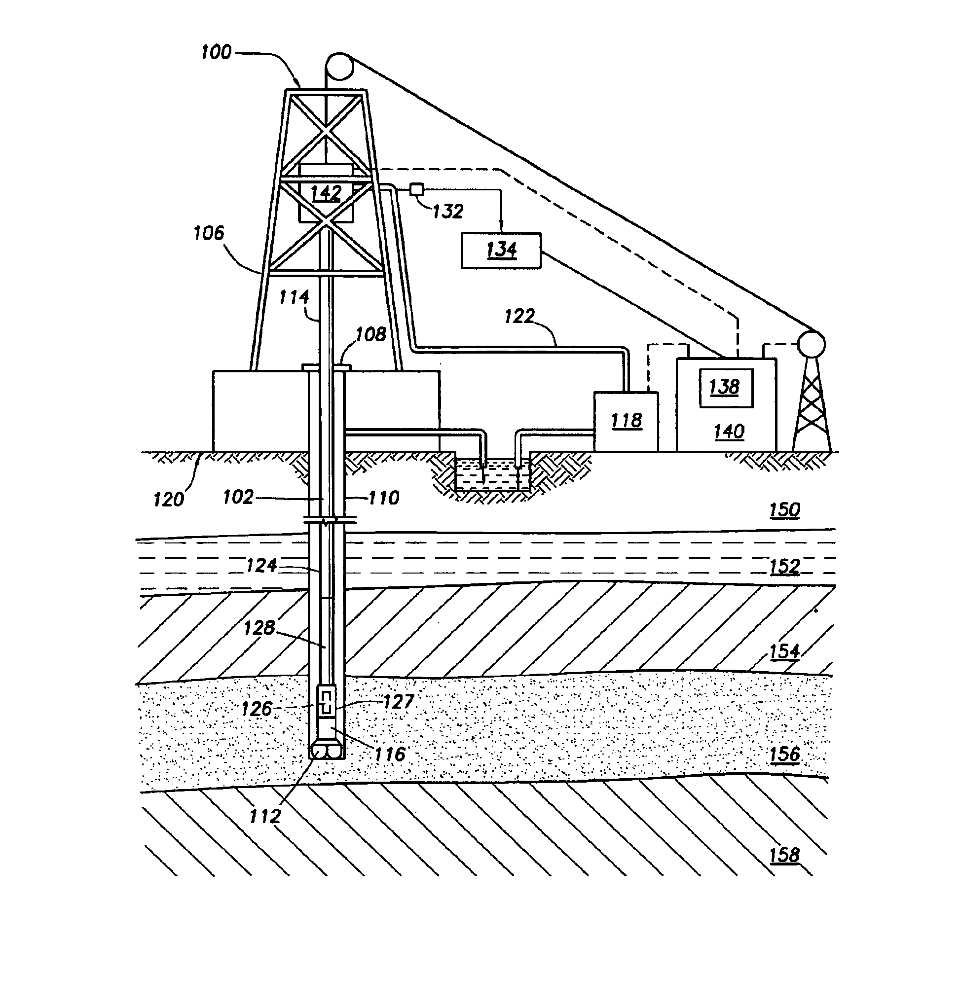
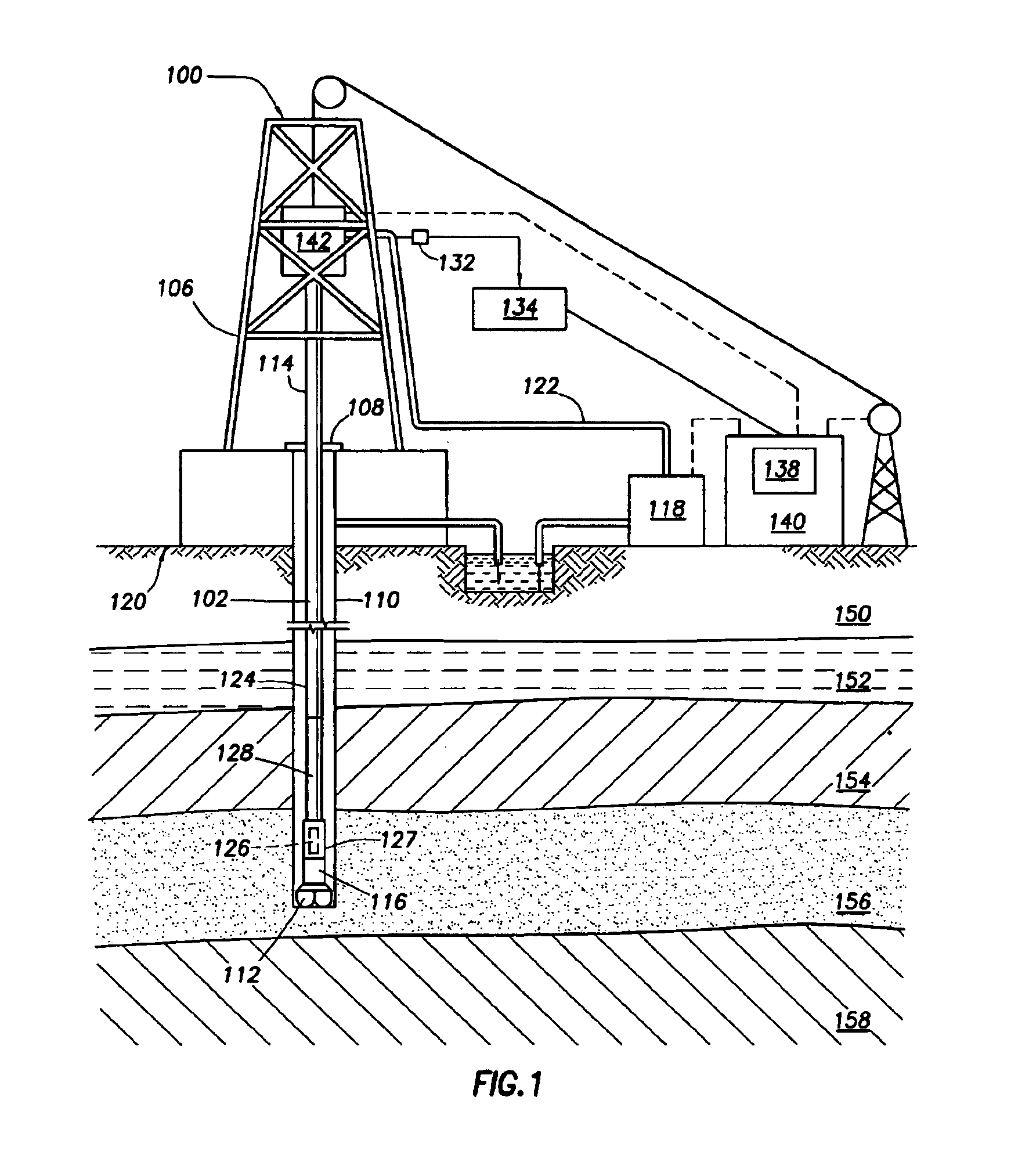
[0021]FIG. 1 illustrates a drilling system 100 that is equipped for communication between a surface control equipment system and down hole measurement systems. As shown in FIG. 1, the drilling system 100 includes a drill string 102 hanging from a derrick 106. The drill string 102 extends through a rotary table 108 into the well 110. A drill bit 112 is attached to the end of the drill s...


PUM


Abstract

A system is for controlling borehole operations using a computational drilling process model representing the combined effect of downhole conditions and the operation of a drillstring. The drilling process model is continually updated with downhole measurements made during a drilling operation. From the updated drilling process model, a set of optimum drilling parameters is determined and communicated to a surface equipment control system. Further, the system allows the surface equipment control system to automatically adjust current surface equipment control settings based on the updated optimum drilling parameters. Various control scripts are generated and executed to inform the surface equipment control system based on a present drilling mode.

Description

CROSS REFERENCE TO RELATED APPLICATIONS[0001]This application claims priority to U.S. provisional application No. 60 / 362,009 filed on Mar. 6, 2002.BACKGROUND OF INVENTION[0002]1. Field of the Invention[0003]The invention relates generally to the field of hydrocarbon drilling system control. More specifically, the invention relates to optimized performance of various drilling operations based on downhole measurements.[0004]2. Background Art[0005]The drilling of oilwells is controlled by the judgment and direct human actions of the driller operating the mechanical and electrical systems of the drilling rig. The driller will typically directly control at the surface control station, for example, drill pipe speed and position, the vertical force applied to drillstring, the rotary speed of the drillstring and the flowrate of the drilling fluid. These parameters, among others, may be controlled within limits such as the physical limitations of the rig equipment, or in some cases, pre-defi...

Claims


Application Information

Patent Timeline
IPC IPC(8): E21B41/00E21B44/00E21B49/00
CPCE21B44/00E21B49/003
Inventor ALDRED, WALTER D.MEEHAN, RICHARD
Owner SCHLUMBERGER TECH CORP
Why Eureka
Try Eureka