

Roadside barrier
a roadside barrier and roadside technology, applied in the direction of shock absorbers, elastic dampers, ways, etc., can solve the problem of immediate deceleration of vehicles, and achieve the effect of eliminating vehicle underride and overrid
Inactive Publication Date: 2010-10-26
AMERICAN VEHICULAR SCI
View PDF30 Cites 12 Cited by
- Summary
- Abstract
- Description
- Claims
- Application Information
AI Technical Summary
Benefits of technology
[0028]It is an object of the present invention to provide a new and improved roadside barrier that eliminates vehicle underride and override.
[0030]It is a further object of this invention to provide a roadside barrier and method for stopping a vehicle after impact into a roadside barrier that gradually decelerates the errant vehicle and brings it to a safe stop.
[0032]A further object of this invention is to provide a roadside barrier that is reusable and can be reinstalled with the minimum cost.
[0037]to provide a new and improved crash attenuator for mounting on a truck or a stationary structure which is efficient in decelerating a vehicle impacting into the attenuator where a constant deceleration is desired;
[0039]to provide a new and improved crash attenuator for mounting on a truck or a stationary structure which enables active control of the rate of energy dissipation in order to better control the deceleration of vehicles impacting the attenuator having widely varying kinetic energy;
Problems solved by technology
Method used
View moreImage
Smart ImageViewing Examples

Examples
example
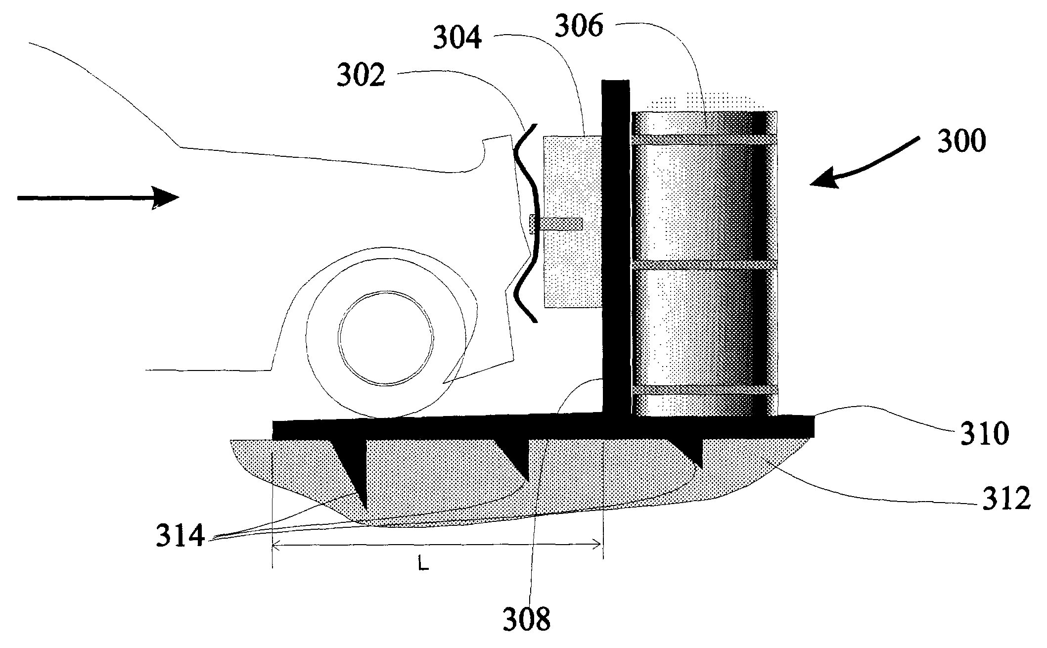
[0213]With the input WT=16000 lbs, W=4400 lbs, A=24 square feet (3 feet by 8 feet), L=10 feet, {dot over (x)}0=62 mph, μ=0.7, pa=14.7 psia, Ta=68 F, CD=0.6, γ=1.4, R=1716.5 fps2 / R,
P1=17.94 psia Equation (9)
X1=1.33 feet Equation (10)=
{dot over (x)}1=61.6 mph Equation (11)
Login to View More PUM
 Abstract
Roadside barrier including barrier sections coupled to one another, each having a horizontal portion, a vertical portion extending upward from the horizontal portion and a front plate coupled to the vertical portion and adapted to receive an impact from a vehicle. The vertical portion extends upward from a middle region of the horizontal portion to form a T-shaped structure. A vehicle impacting the front plate is situated on a front part of the horizontal portion thereby preventing the vehicle from tipping over. A mass, such as gravel or sand, is placed on a rear part of the horizontal portion, either loose or in a barrel or box. The barrier section is optionally designed to provide an increased drag once moved from its installation position, for example, by forming downwardly-extending protrusions on a lower surface of the horizontal portion which are adapted to penetrate the ground below the barrier section.
Description
CROSS REFERENCE TO RELATED APPLICATIONS[0001]This application is a continuation-in-part of U.S. patent application Ser. No. 10 / 028,354 filed Dec. 24, 2001 which in turn is a continuation-in-part of U.S. patent application Ser. No. 09 / 811,712 filed Mar. 19, 2001, now U.S. Pat. No. 6,343,821, which in turn is a continuation of U.S. patent application Ser. No. 09 / 200,367 filed Nov. 23, 1998, now U.S. Pat. No. 6,203,079.[0002]This application claims domestic priority of U.S. provisional patent application Ser. No. 60 / 066,486 filed Nov. 24, 1997 through the '354 application, the '712 application and the '367 application.[0003]All patents and literature referenced herein in incorporated herein by reference as if the entire contents were reproduced and inserted at the reference point.FIELD OF THE INVENTION[0004]The present invention relates in general to roadside barriers such as crash cushions (sand-filled yellow barrels) and Bullnose Median Barriers as well as crash attenuators, and more...
Claims
Login to View More Application Information
Patent Timeline
 Patent Type & AuthorityPatents(United States)
IPC IPC(8): E01F13/02E01F15/08B60R19/00B60R19/20B60R19/40B60R21/01B60R21/0134B60R21/0136E01F9/012E01F15/14F16F7/12F16F9/04
CPCB60R19/00E01F9/0126E01F15/146E01F15/148F16F7/121F16F9/0472B60R19/20B60R19/40B60R21/0134B60R21/0136B60R2019/005B60R2019/007E01F9/662
InventorBREED, DAVID S.
OwnerAMERICAN VEHICULAR SCI