System and method for MR imaging in inhomogeneous magnetic fields

a technology imaging system, applied in the field of magnetic resonance imaging, can solve the problems of inhomogeneous magnetic field, drastic distortion of readout and slice directions, and generally unacceptable clinical evaluation

Active Publication Date: 2010-10-26
GENERAL ELECTRIC CO
View PDF6 Cites 22 Cited by
  • Summary
  • Abstract
  • Description
  • Claims
  • Application Information

AI Technical Summary

Benefits of technology

[0010]In accordance with yet another aspect of the invention, a computer readable storage medium having stored thereon a computer program includes instructions which when executed by a computer cause the computer to set a center transmission frequency and a center reception frequency of a first 3D MR acquisition equal to a first center frequency offset and to execute the first 3D MR acquisition to acquire a first set of 3D MR data. The instructions also cause the computer to set a center transmission frequency and a center reception frequency of a second 3D MR acquisition equal to a second center frequency offset different than the first center frequency offset and to execute the second 3D MR acquisition to acquire a second set of 3D MR data. The instructions further cause the computer to reconstruct a composite image based on the first and second sets of 3D MR data.

Problems solved by technology

Using magnetic resonance imaging to assist in clinical diagnostics of MR-compatible arthroplastic implants, however, has proven a fundamentally challenging problem.
Accordingly, these materials can introduce distortions in the main magnetic field resulting in an inhomogeneous magnetic field.
While the signal loss induced by these field gradients can largely be regained through the use of Hahn spin-echoes, the distortion they produce in both the readout and slice directions are drastic and are typically unacceptable for clinical evaluation.
Unfortunately, artifacts induced by the implants in conventional MRI images are most severe near the implant interfaces.
Though this approach can improve in-plane distortions at the cost of significant image blurring, it does not address distortions in the slice-selection direction.
While a slice-distortion correction of VAT images in the slice direction has been proposed, its use is limited because it does not correct signal-pileup effects of image distortion.

Method used


Image

  • System and method for MR imaging in inhomogeneous magnetic fields
  • System and method for MR imaging in inhomogeneous magnetic fields
  • System and method for MR imaging in inhomogeneous magnetic fields

Examples


Embodiment Construction

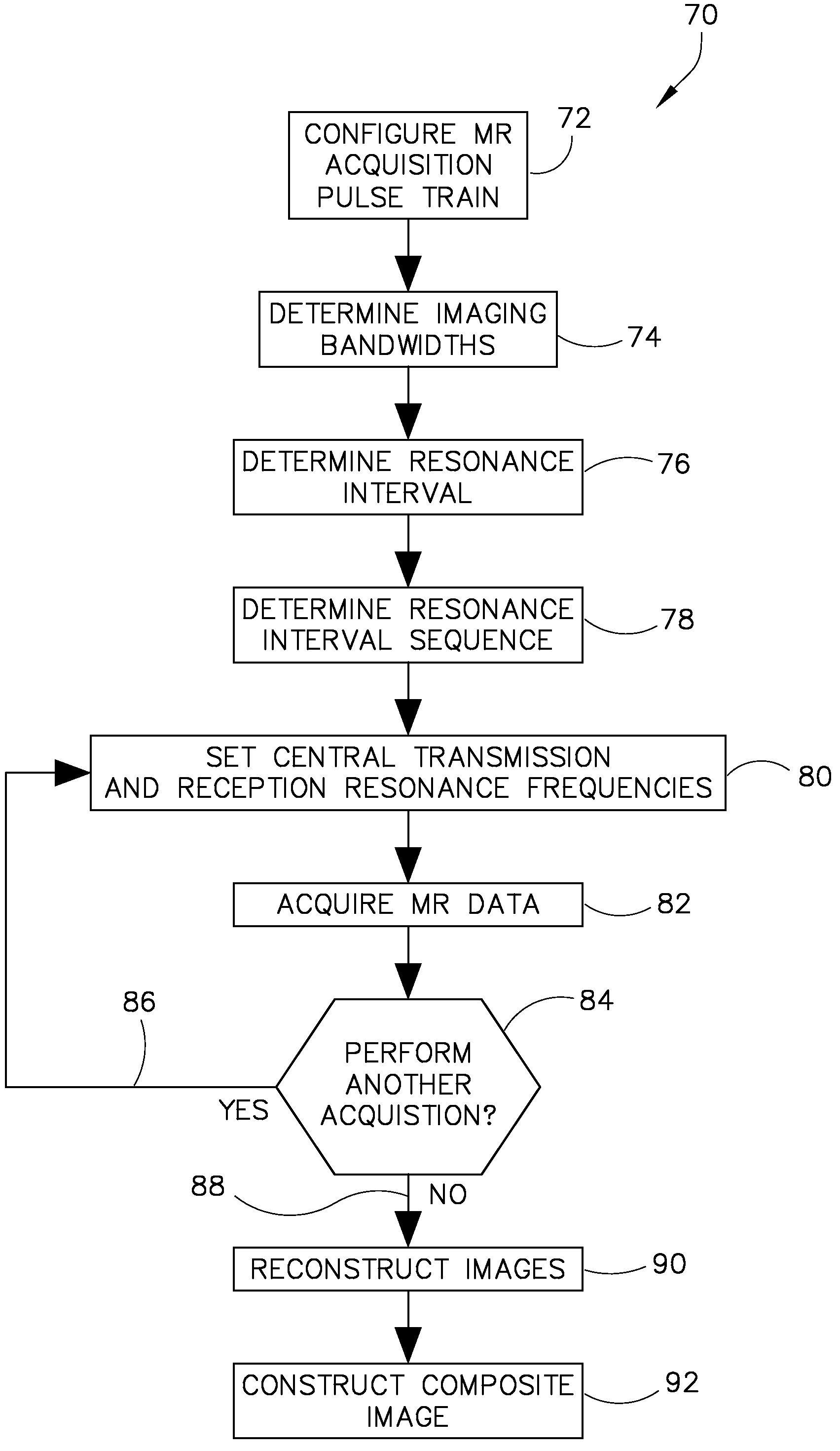
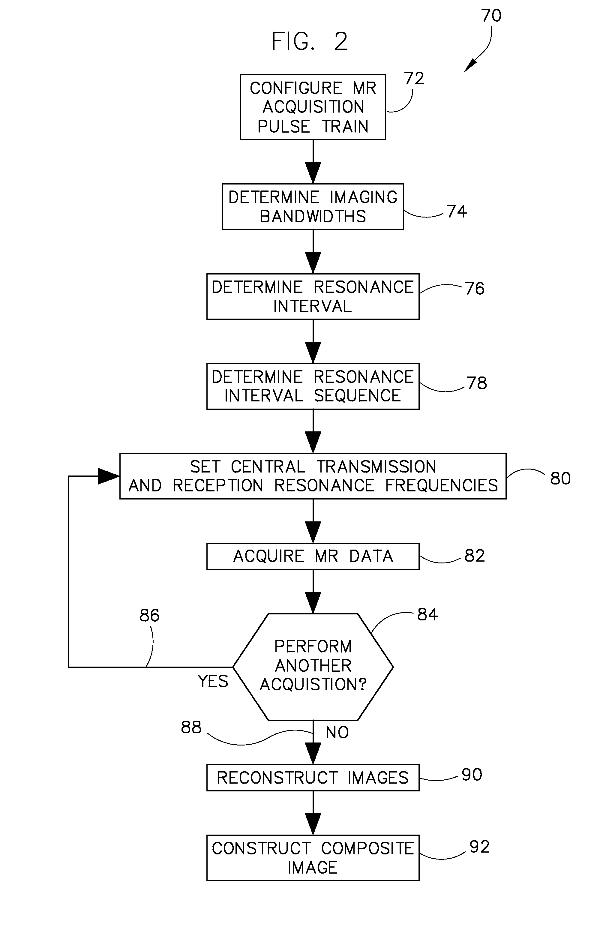
[0017]An apparatus and method is provided that acquires multiple 3D MR data sets where the center transmission frequency and the center reception frequency of each 3D MR data acquisition are set to an offset frequency that is distinct for each 3D MR data set. A single image is constructed from the 3D MR data sets having reduced artifacts and reduced image distortion.

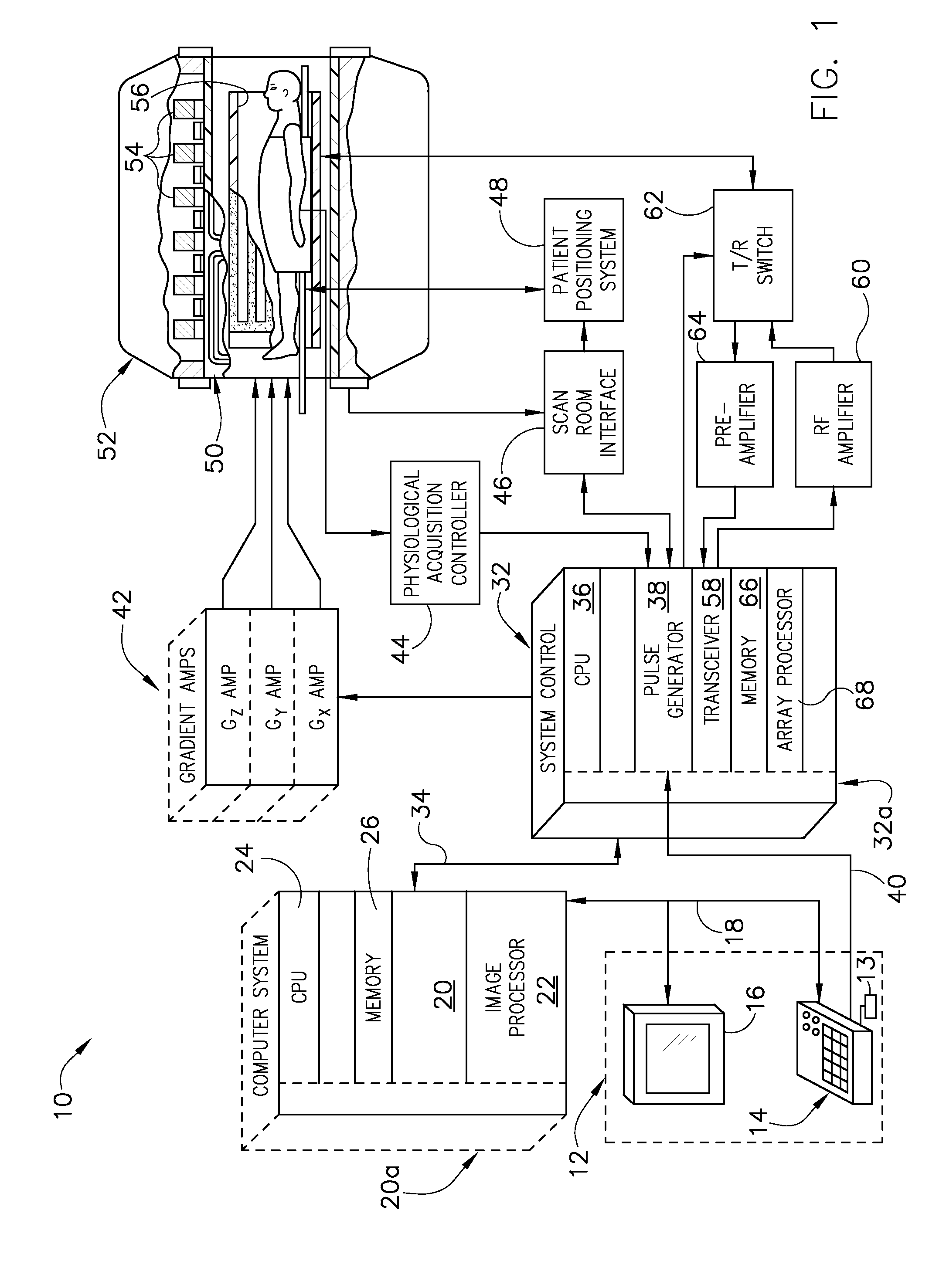
[0018]Referring to FIG. 1, the major components of an exemplary magnetic resonance imaging (MRI) system 10 incorporating embodiments of the present invention are shown. The operation of the system is controlled from an operator console 12 which includes a keyboard or other input device 13, a control panel 14, and a display screen 16. The console 12 communicates through a link 18 with a separate computer system 20 that enables an operator to control the production and display of images on the display screen 16. The computer system 20 includes a number of modules which communicate with each other through a backplane 20a. T...


PUM


Abstract

An apparatus and method for MR imaging in inhomogeneous magnetic fields includes acquisition of a plurality of three-dimensional (3D) MR data sets, each data set having a central transmit frequency and a central receive frequency set to a frequency offset that is distinct for each 3D MR data set. A composite image is generated based on the plurality of 3D MR data sets.

Description

BACKGROUND OF THE INVENTION[0001]The present invention relates generally to magnetic resonance (MR) imaging and, more particularly, MR imaging in inhomogeneous magnetic fields.[0002]When a substance such as human tissue is subjected to a uniform magnetic field (polarizing field B0), the individual magnetic moments of the spins in the tissue attempt to align with this polarizing field, but precess about it in random order at their characteristic Larmor frequency. If the substance, or tissue, is subjected to a magnetic field (excitation field B1) which is in the x-y plane and which is near the Larmor frequency, the net aligned moment, or “longitudinal magnetization”, MZ, may be rotated, or “tipped”, into the x-y plane to produce a net transverse magnetic moment Mt. A signal is emitted by the excited spins after the excitation signal B1 is terminated and this signal may be received and processed to form an image.[0003]When utilizing these signals to produce images, magnetic field gradi...

Claims


Application Information

Patent Timeline
Patent Type & Authority Patents(United States)
IPC IPC(8): G01V3/00
CPCG01R33/243G01R33/4822G01R33/56563G01R33/5608
Inventor KOCH, KEVIN M.KING, KEVIN F.BUSSE, REED F.
Owner GENERAL ELECTRIC CO
Why Eureka
Try Eureka